Device for determining the longitudinal and angular position of a rotationally symmetrical apparatus

a rotationally symmetrical and apparatus technology, applied in the direction of measurement devices, converting sensor output, medical science, etc., can solve the problems of increasing manufacturing costs, limiting the type of instruments and surfaces that can be tracked, and unable to accurately determine the longitudinal and angular position of the apparatus

Inactive Publication Date: 2005-04-07
XITACT
View PDF24 Cites 83 Cited by
  • Summary
  • Abstract
  • Description
  • Claims
  • Application Information

AI Technical Summary

Benefits of technology

[0012] The present invention relates on the insight that optical navigation sensors which are used in so-called optical mice for flat surfaces can be applied to tracking the motion of a rotationally symmetrical instrument to accurately determine its longitudinal and angular position—by measuring the motion of the instrument, and providing a means of establishing its absolute position.

Problems solved by technology

Furthermore, some motion measurements systems accumulate a measurement error, so periodic identification of a reference position may be required.
While such systems provide a reliable measurement of the instrument's motion, potentially without any accumulated error, the need to establish a reference position is typically present.
This approach allows a contact-free reading of the motion of the instrument, but can only track specially designed surfaces.
This increases manufacturing costs, and limits the type of instruments and surfaces that can be tracked.
The surface coating also needs to be protected, as stains or scratches are likely to interfere with the tracking.
The resolution that can be obtained with such a system is also limited.

Method used


Image

  • Device for determining the longitudinal and angular position of a rotationally symmetrical apparatus
  • Device for determining the longitudinal and angular position of a rotationally symmetrical apparatus
  • Device for determining the longitudinal and angular position of a rotationally symmetrical apparatus

Examples


Embodiment Construction

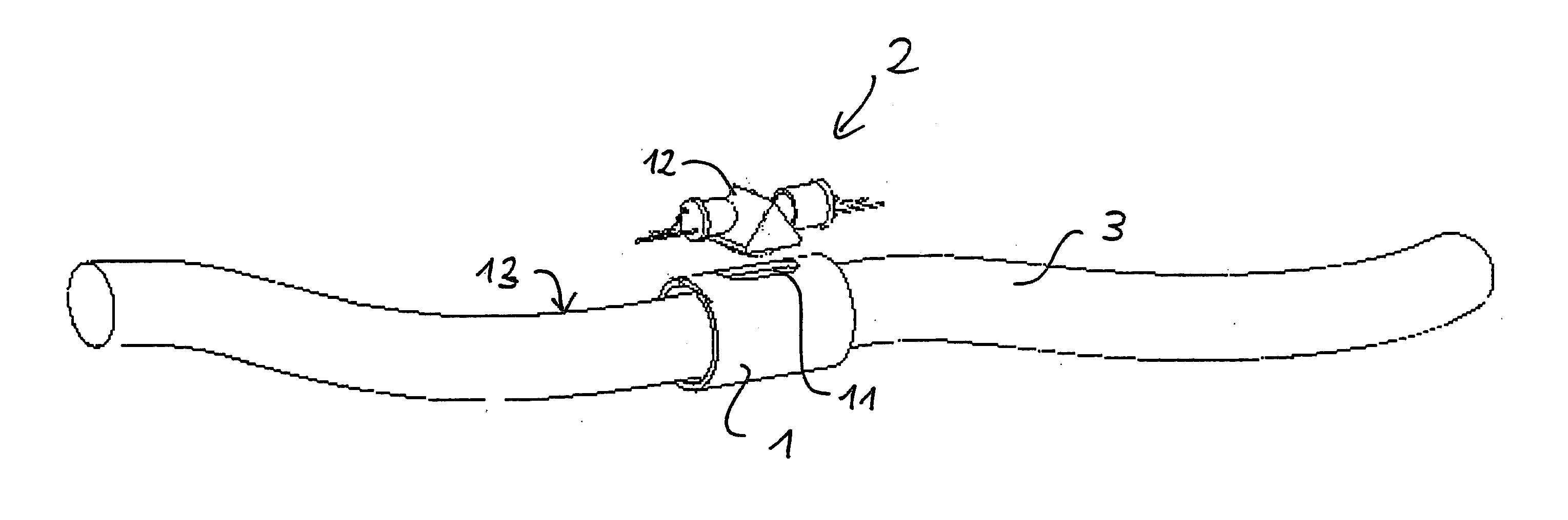
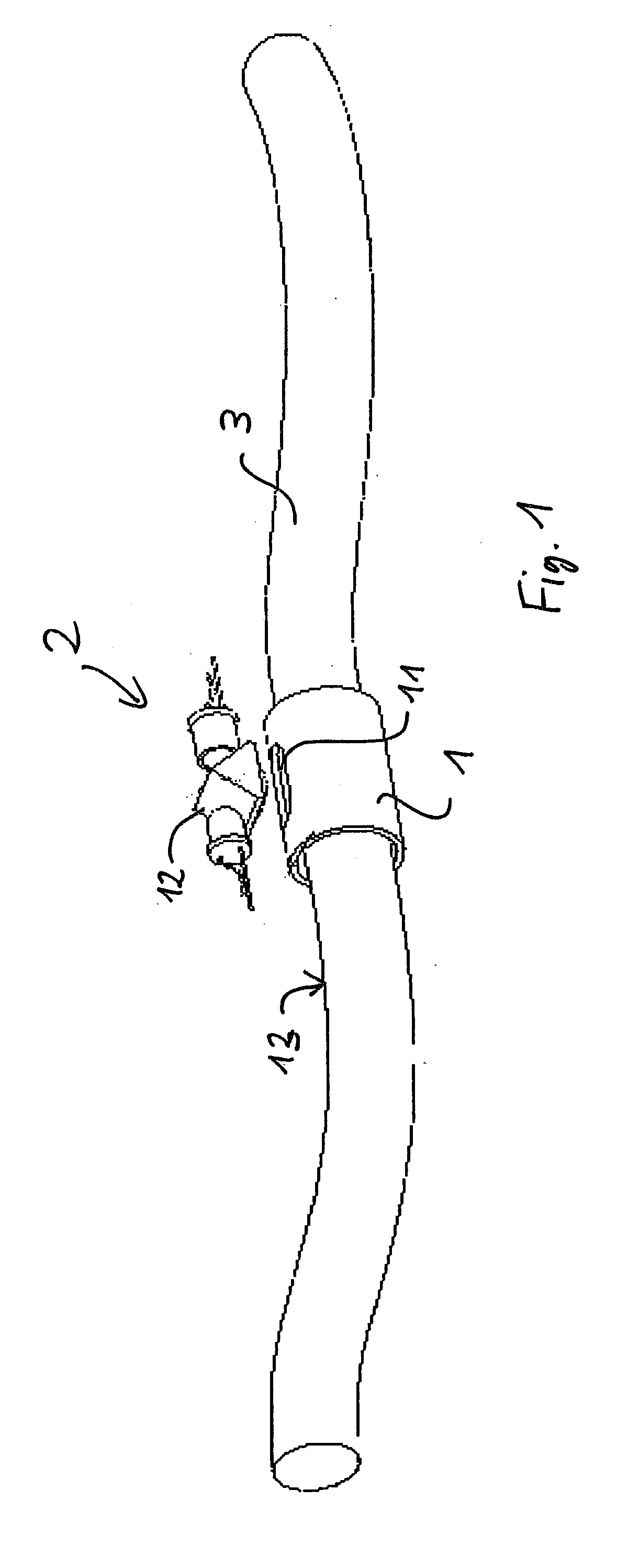
[0026]FIG. 1 shows a schematic view of an externally mounted optical tracking device according to one embodiment of the invention.

[0027] An instrument-holding device 1 contains an opening or transparent area 11 through which an optical navigation sensor 2 can track the underlying surface 13 of an inserted instrument 3. The holding device 1 can have various shapes. In particular, it can be similar to any existing instrument trocar used during medical procedures, some of which allow the insertion of instruments of varying diameters. The instrument-holding device 1 is preferably a hollow cylindrical element. It may be a short sleeve allowing the introduction of a flexible element or instrument 3 as shown in FIG. 1. The opening or transparent area 11 within the instrument-holding device 1 is at least as large as the maximum field of vision of the imaging optical navigation sensor 2; alternatively the whole holding device 1 could be transparent. The underlying surface 13 has a non-negli...


PUM


Abstract

A device for determining the longitudinal and angular position of a rotationally symmetrical apparatus when guided inside a longitudinal element surrounding the same, including an imaging optical navigation sensor that measures the motion of the underlying surface by comparing successive images, and translates this image translation into a measurement of the longitudinal and rotational motion of the instrument. Features of the captured image are used to identify the insertion or withdrawal of the instrument, and to identify specific areas of the moving surface passing underneath the sensor, therefore allowing to establish the absolute position of the instrument, or to identify which instrument was inserted or in what cavity a tracking instrument was inserted. The device comprises a light source and a light detector. Light emitted by said light source is directed onto a surface of the rotationally symmetrical apparatus. Reflected light from said surface is detected by said light detector to produce a position signal showing a locally varying distribution in the longitudinal direction and in the peripheral direction to enable said precise position and angular measurement.

Description

FIELD OF THE INVENTION [0001] The present invention relates to a device for determining the longitudinal and angular position of a rotationally symmetrical apparatus used for simulated or real surgical operations and especially an optical navigation sensor tracking the motion of the surface of an instrument as it passes through a static element that surrounds it, such as a trocar, a needle or a vessel. BACKGROUND OF THE INVENTION [0002] Surgery simulators, as well computer assisted surgery systems and other applications, require that the position of instruments manipulated by users be continuously tracked. In minimally invasive surgical procedures, where instruments pass through an insertion port, such as a trocar or needle, it is common that the motion of an instrument relative to that insertion port needs to be continuously measured and defined, or “tracked”. [0003] This tracking typically requires two types of information: (1) the continuous and precise measurement of the motion ...

Claims


Application Information

Patent Timeline
Patent Type & Authority Applications(United States)
IPC IPC(8): G01D5/347
CPCG01D5/34776G01D5/347
Inventor VECERINA, IVANZOETHOUT, JURJENBETRISEY, STEPHANE
Owner XITACT
Why Eureka
Try Eureka