Multi-axis sector motor

Active Publication Date: 2014-09-18
DRS NETWORK & IMAGING SYST
View PDF6 Cites 6 Cited by
  • Summary
  • Abstract
  • Description
  • Claims
  • Application Information

AI Technical Summary

Benefits of technology

[0007]Numerous benefits are achieved by way of exemplary embodiments of the present invention over conventional techniques. For example, exemplary embodiments of the present invention provide a fine axis sector motor that can actuate two axes of motion with a single compact device. The compact fine axis sector motor, which may be connected to an optical payload, provides for precise adjustment/movement of the payload over small angles for stabilization while gener

Problems solved by technology

An optical device may be stabilized when attached to an aircraft or other hi

Method used


Image

  • Multi-axis sector motor
  • Multi-axis sector motor
  • Multi-axis sector motor

Examples


Example

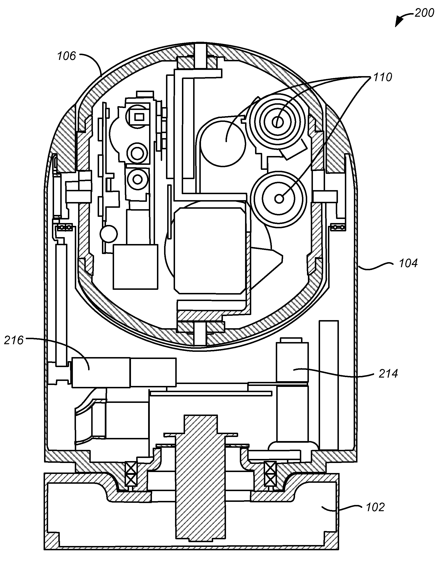
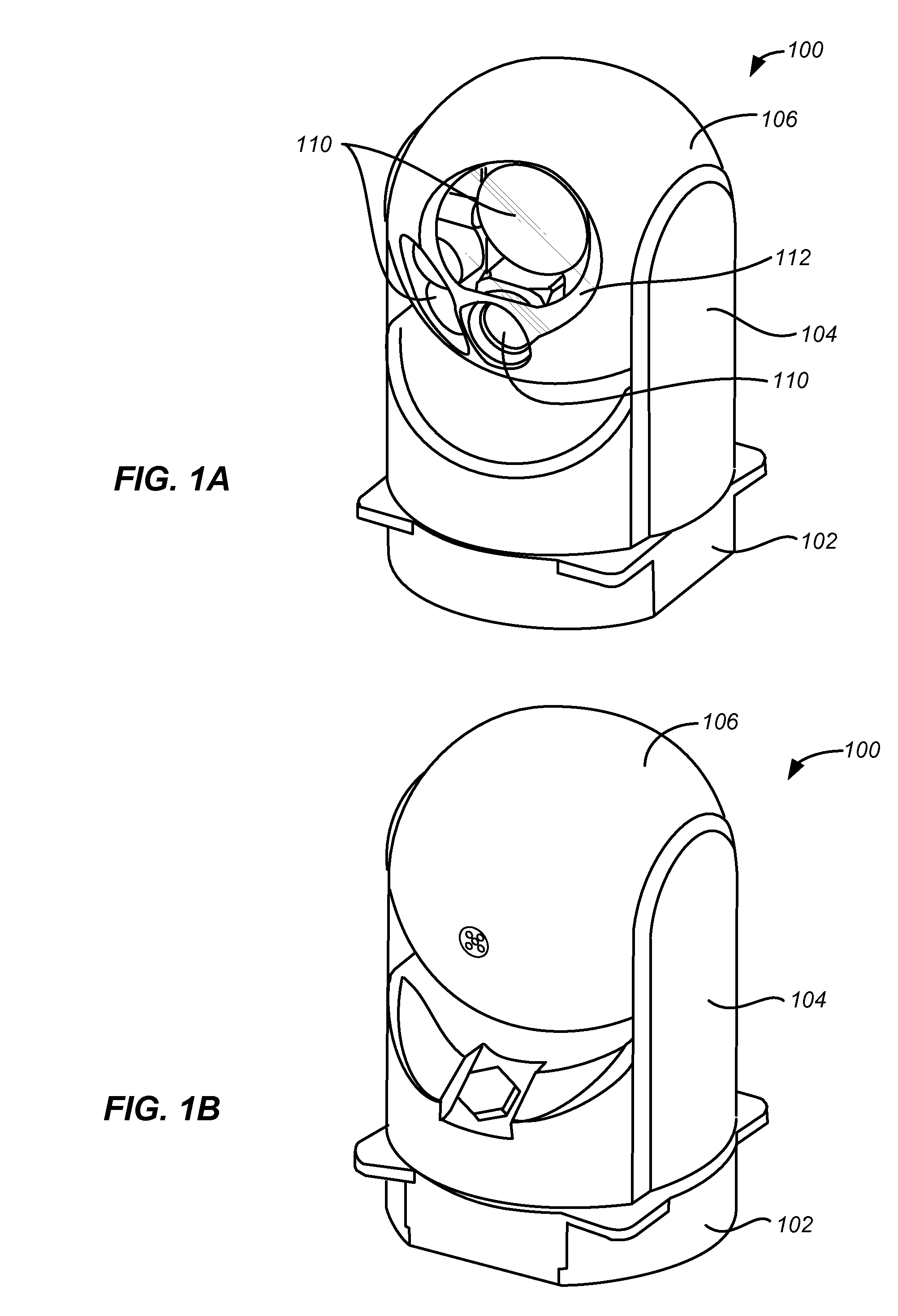
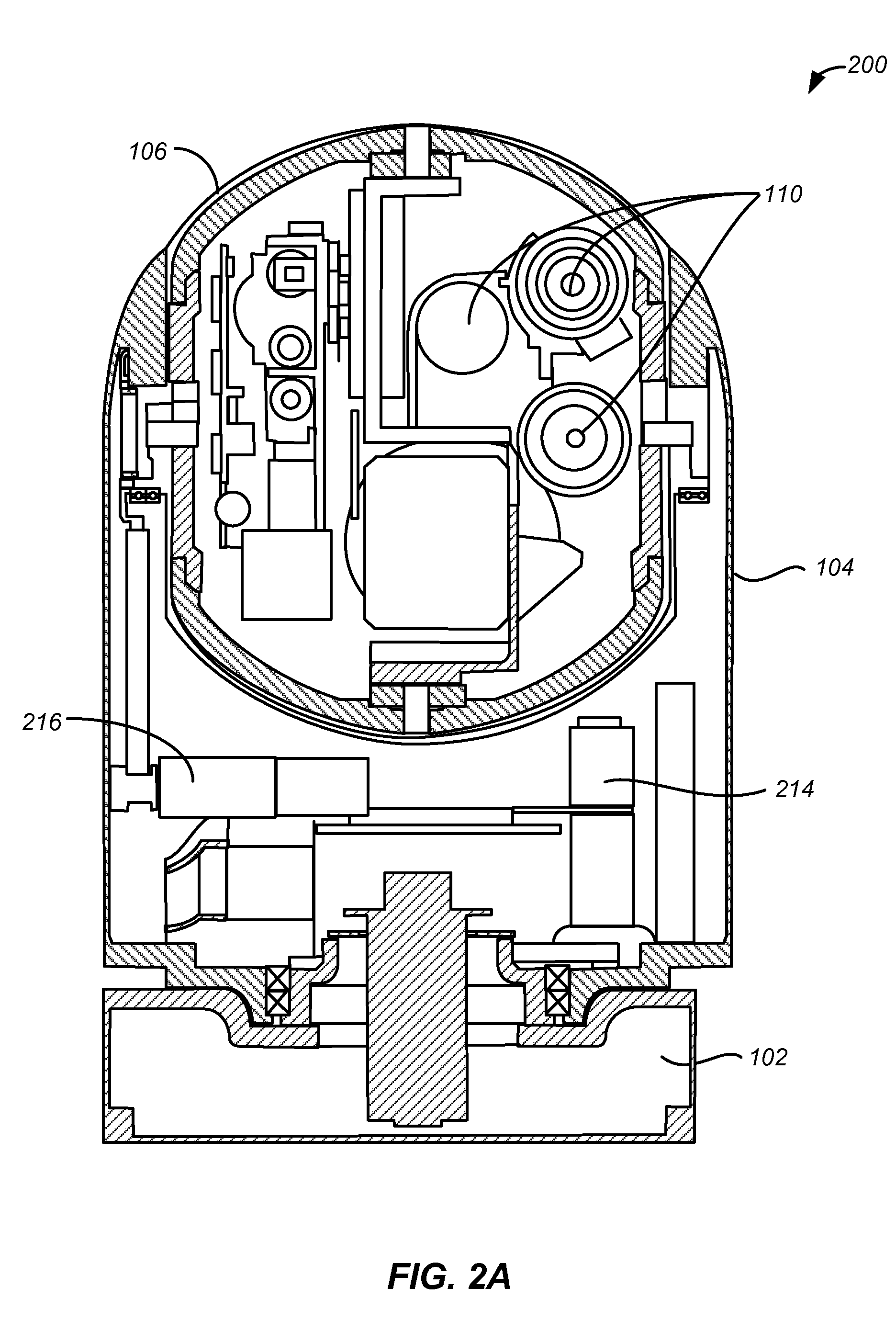
[0023]Exemplary embodiments of the present invention provide a multi-axis motor system including a four-axis gimbal. The four-axis gimbal may include, for example, two coarse axes combined with two fine axes to stabilize a payload, such as an optical payload. The two fine axes may include, for example, an azimuth axis orthogonal to an elevation axis. The multi-axis motor system includes a sector motor that positions the two fine axes of the gimbal. The sector motor provides a predetermined (e.g., limited) range (e.g. + / −2°) of angular motion, relative to the coarse axis structure, concurrently in both of the fine axes.

[0024]While exemplary embodiments describe the use of the systems and methods described herein in the context of fine axis motor control to provide orthogonal tangential forces to position and stabilize the optical payload of a gimbal system, the motor design is equally applicable to any situation requiring precise application of force to move (or to prevent movement) ...


PUM


Abstract

A multi-axis motor includes a first elongate magnet member disposed in a first orientation and a second elongate magnet member disposed in a second orientation orthogonal to the first orientation and mechanically coupled to the first elongate magnet member. The first elongate magnet member is operable to adjust a first axis of a fine axis structure. The second elongate magnet member is operable to adjust a second axis of the fine axis structure.

Description

CROSS-REFERENCES TO RELATED APPLICATIONS[0001]This application claims priority to U.S. Provisional Patent Application No. 61 / 782,905, filed Mar. 14, 2013, entitled “Multi-Axis Sector Motor,” the disclosure of which is hereby incorporated by reference in its entirety for all purposes.BACKGROUND OF THE INVENTION[0002]An optical device may be stabilized when attached to an aircraft or other high volatile systems and traditional coarse stabilizers may not be sufficient. Therefore, there is a need in the art for improved methods and systems to efficiently fine tune and stabilize such an optical device system.SUMMARY OF THE INVENTION[0003]Exemplary embodiments of the present invention relate generally to electrical systems. More specifically, exemplary embodiments of the present invention relate to a multi-axis motor suitable for providing fine control over the position of an object. In an embodiment, a system including a fine stabilizer operable to adjust the position of the optical devi...

Claims


Application Information

Patent Timeline
IPC IPC(8): G02B27/64H02K1/06
CPCH02K1/06G02B27/64H02K41/0358H02K7/14H02K2201/18H02K2213/03
Inventor PEKAREK, BRIAN R.WOODALL, MILTON A.ROYALTY, JIM
Owner DRS NETWORK & IMAGING SYST
Why Eureka
Try Eureka