Vibration/noise management in a scroll compressor

Active Publication Date: 2014-09-18
AGILENT TECH INC
View PDF6 Cites 16 Cited by
  • Summary
  • Abstract
  • Description
  • Claims
  • Application Information

AI Technical Summary

Benefits of technology

[0018]In addition, the pump can be placed in a second mode in which the feet are resting against a support surface while the pump head/motor assembly is not locked to the sound-muffling enclosure and the sound-muffling enclosure is locked to the support surface independently of the feet. Accordingly, the sound-muffling enclosure can be hard mounted to the support surface such that it can not move relative to the support surface while the pump head/motor assembly is free mounted to the sound-muffling enclosure via the vibration isolation system such that the pump head/motor assembly can vibrate relative to the sound-muffling enclosure and support surface.
[0019]This second mode may be the operational configuration of the pump when it is an integrated component of a larger piece of machinery, i.e., the second mode may be what is referred to as an integrated component in operational mode. In this case, the support surface would typically be a structural surface within the larger piece of machinery. This mode allows the pump head/motor assembly to vibrate within the sound-muffling enclosure without transmitting vibrations to the equipment or noise to the operator of the equipment, while the pump is nonetheless securely fastened to the support surface in the equipment.
[0020]In addition, the pump can be placed in a third mode, i.e. bench top operational mode, in which the feet are resting against a support surface while the pump head/motor assembly is not locked to the sound-muffling enclosure. Accordingly, the sound-muffling enclosure is not hard mounted to the support surface and can be located and moved as required while the pump head/motor assembly is free mounted to the sound-muffling enclosure via the vibration isolation system

Problems solved by technology

In any case, the rotary components of the pump head and motor produce vibrations.
These vibrations, in turn, can generate sound waves, i.e., the rotary component

Method used


Image

  • Vibration/noise management in a scroll compressor
  • Vibration/noise management in a scroll compressor
  • Vibration/noise management in a scroll compressor

Examples


Example

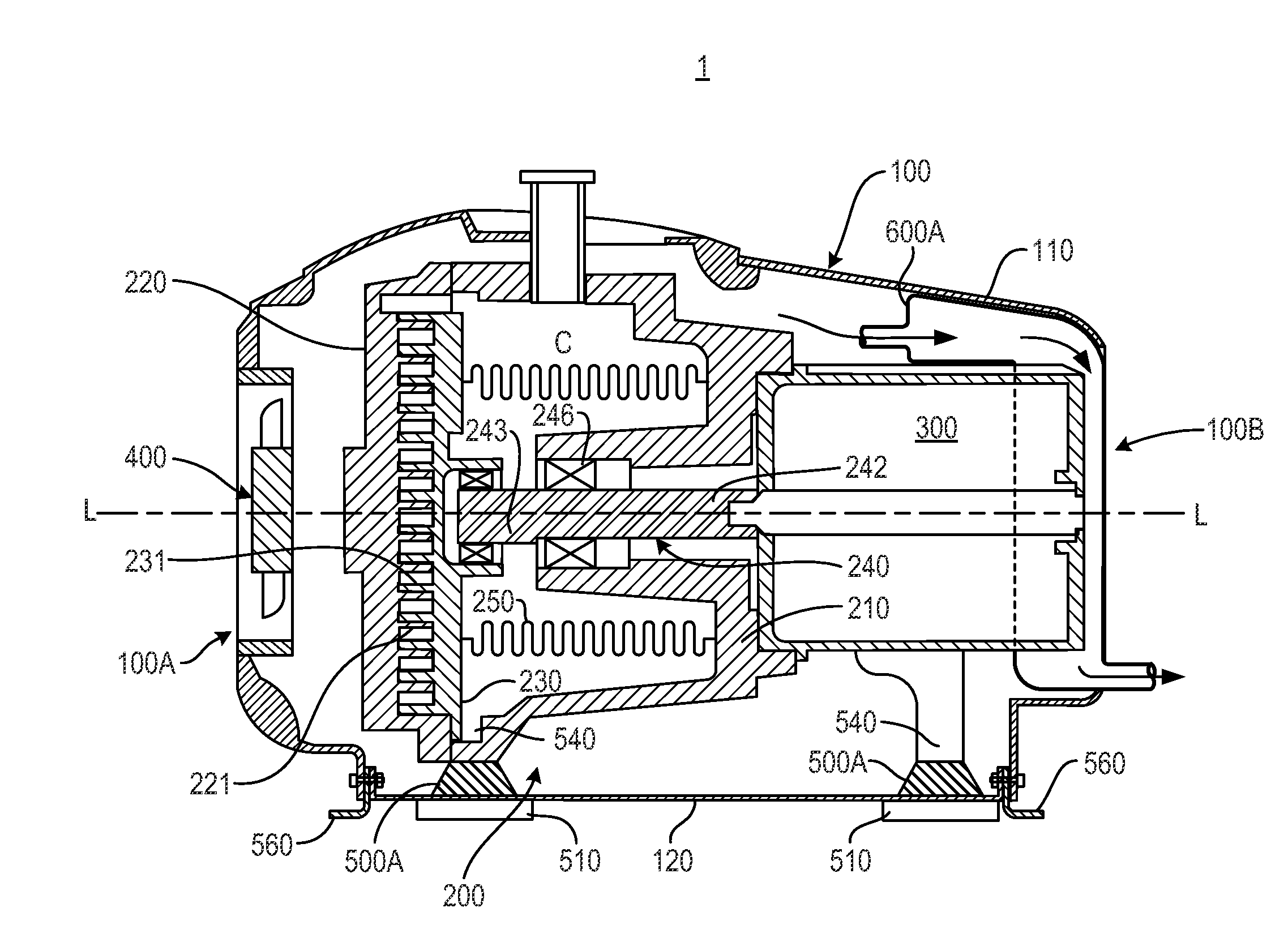
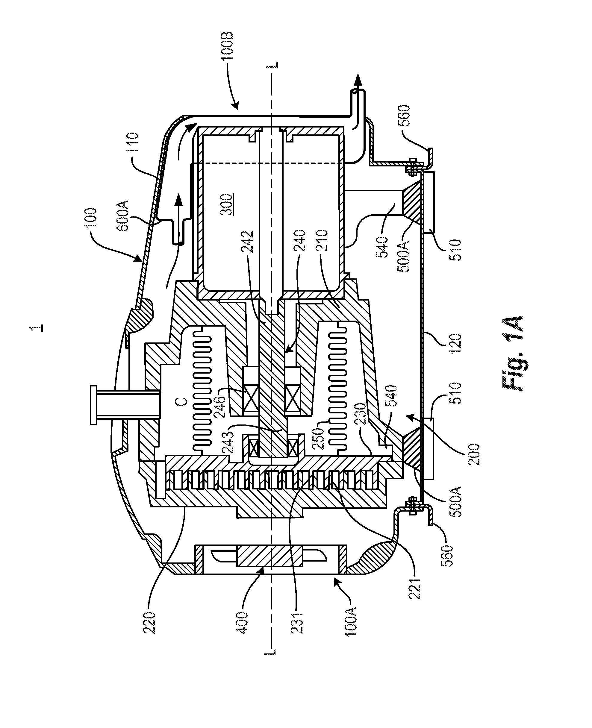
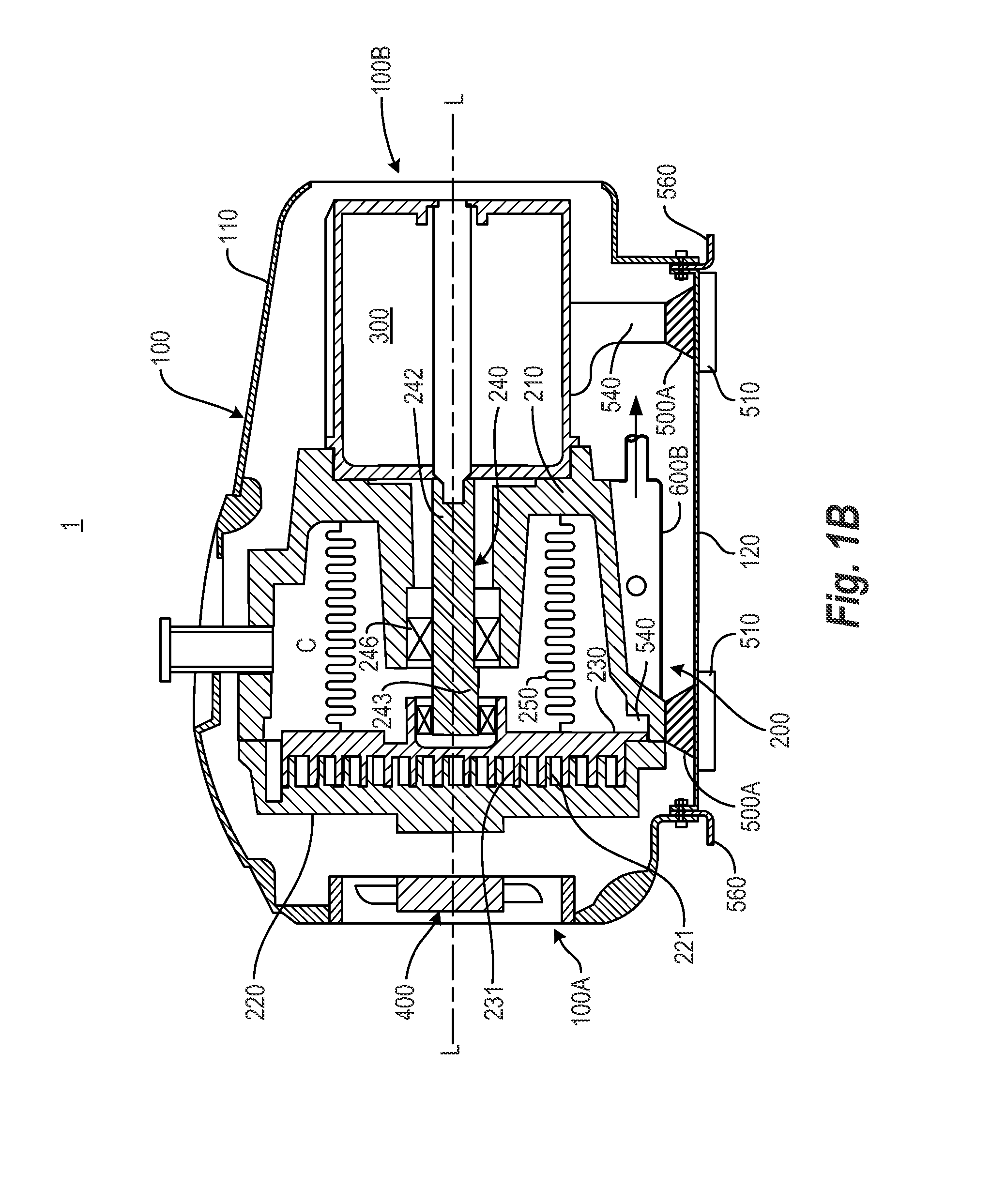
[0030]Various embodiments and examples of embodiments of the inventive concept will be described more fully hereinafter with reference to the accompanying drawings. In the drawings, the sizes and relative sizes of elements may be exaggerated for clarity. Likewise, the shapes of elements may be exaggerated and / or simplified for clarity and ease of understanding. Also, like numerals and reference characters are used to designate like elements throughout the drawings.

[0031]Furthermore, terminology used herein for the purpose of describing particular examples or embodiments of the inventive concept is to be taken in context. For example, the terms “comprises” or “comprising” when used in this specification indicates the presence of stated features or processes but does not preclude the presence of additional features or processes. The term “pump” may refer to apparatus that drives, or raises or decreases the pressure of a fluid, etc. The term “fixed” may be used to describe a direct con...


PUM


Abstract

A scroll pump isolates vibrations of a pump head/motor assembly of the pump from the exterior of the pump and thus, suppresses the production of airborne noise. The pump includes a sound-muffling enclosure surrounding the pump head/motor assembly, feet supporting the enclosure, and elastic vibration isolators. The pump head/motor assembly is fixed to the tops of the vibration isolators, and the sound-muffling enclosure is fixed to the vibration isolators at the bottoms of the isolators. The scroll pump also has a locking system by which motion of the pump head/motor assembly relative to the sound-muffling enclosure can be limited or prevented, and by which the sound-muffling enclosure can be hard-mounted to a support surface independently of the feet.

Description

BACKGROUND[0001]1. Field of the Invention[0002]The present invention relates to a scroll pump having a pump head / motor assembly that includes a stationary plate scroll having a stationary scroll blade, an orbiting plate scroll having a scroll blade nested with the stationary scroll blade, and a pump motor having a rotary output coupled to the orbiting plate scroll so as to drive the orbiting scroll blade relative to the stationary scroll blade. In particular, the present invention relates to a scroll pump having a system that reduces the noise and vibration produced by the pump head / motor assembly.[0003]2. Description of the Related Art[0004]A scroll pump is a type of pump that includes a stationary plate scroll having a stationary plate and a spiral stationary scroll blade projecting axially therefrom, and an orbiting plate scroll having an orbiting plate and a spiral orbiting scroll blade projecting axially therefrom. The stationary and orbiting scroll blades are nested with a cle...

Claims


Application Information

Patent Timeline
IPC IPC(8): F04C15/00
CPCF04C15/0057F04C29/066F04C18/0215F04C2270/12F04C29/068F04C2270/125
Inventor CALHOUN, JOHNFORNI, RONALD J.GALICA, GEORGELU, VANNIE (YUCONG)
Owner AGILENT TECH INC
Why Eureka
Try Eureka