Electrochemical device for syngas and liquid fuels production

a technology of electrochemical devices and liquid fuels, which is applied in the direction of oxygen compound preparation by reduction, climate sustainability, energy input, etc., can solve the problems of achieve the effect of reducing soec operational costs and syngas produced unit cos

Inactive Publication Date: 2014-09-18
ALLIANCE FOR SUSTAINABLE ENERGY +1
View PDF5 Cites 51 Cited by
  • Summary
  • Abstract
  • Description
  • Claims
  • Application Information

AI Technical Summary

Benefits of technology

[0013]The present invention discloses a novel fuel production method that integrates an optimized upstream, high temperature solid oxide co-electrolysis system for the production of clean syngas from carbon dioxide and steam with a downstream gas-to-liquid conversion process to produce liquid hydrocarbon fuels. One aspect of the present invention is a novel heat integration method that utilizes a fraction of the liquid fuel produced to provide the SOEC's thermal energy requirements. In addition, the present invention discloses further integration between the up- and downstream processes, which generates steam, reuses plant water, and recycles Some or all of the hydrogen derived from the syngas and fuel synthesis processing steps back to the SOEC. This hydrogen recycle reduces SOEC operational costs and, therefore, the unit cost of the syngas produced.

Problems solved by technology

This hydrogen recycle reduces SOEC operational costs and, therefore, the unit cost of the syngas produced.

Method used


Image

  • Electrochemical device for syngas and liquid fuels production
  • Electrochemical device for syngas and liquid fuels production
  • Electrochemical device for syngas and liquid fuels production

Examples


example 1

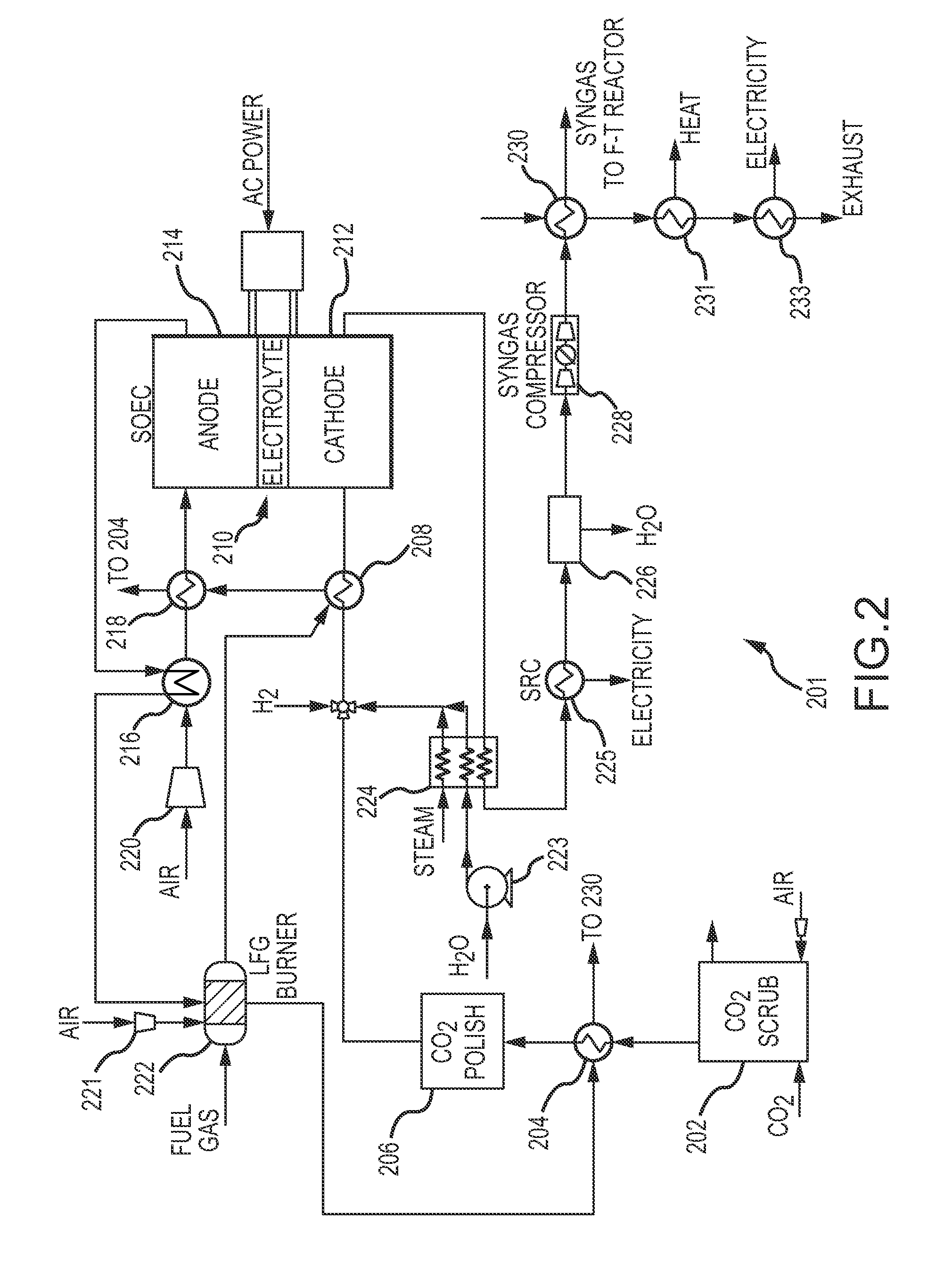
[0066]Table 1 provides estimated temperatures for streams at different points in the system 201. One having skill in the art would understand that the temperatures, pressures and flow rates may be altered without deviating from the invention. Thus, the values listed in Table 1 are not intended to limit the scope of the present invention. These process conditions may vary significantly around the values reported in the stream tables, by as much as ±20%, and / or as described elsewhere in this disclosure.

TABLE 1Example stream properties for system illustrated in FIG. 2.StreamTemperaturePressureFlow rate(° C.)(kPa)(kg / s)CO2 entering 202202003.88Scrubbed feed stream201903.85Preheated feed stream3751803.85Polished feed stream3751703.85Water entering compressor301000.63223Water exiting compressor301800.63223Steam exiting heat6001703.02exchanger 224Combined stream entering4951706.89heat exchanger 208Heated compressed stream8001606.89exiting heat exchanger 208and entering SOEC 210 atcathode 2...

example 2

[0067]Table 2 provides estimated temperatures, pressures and flow rates for streams at different locations in the system 334. One having skill in the art would understand that the temperatures, pressures and flow rates may be altered without deviating from the invention. Thus, the values listed in Table 2 are not intended to limit the scope of the present invention. These process conditions may vary significantly around the values reported in the stream tables, by as much as ±20%, and / or as described elsewhere in this disclosure.

TABLE 2Example streams properties for system illustrated in Figure 3.StreamT (° C.)Pressure (kPa)Flow rate (kg / s)Syngas entering FT reactor24039902.99336Steam exiting FT reactor22525002.38336Gas entering heat24038902.99exchanger 346Syngas entering WGS24039900.06reactor 338LFG (may be directed to4036001.04LFG mixer 342)Gas entering the WGS4036000.46reactor 338Gas entering H2 separator4034800.73system 340Hydrogen gas exiting4034200.02hydrogen separationchamber...


PUM

PropertyMeasurementUnit
temperatureaaaaaaaaaa
pressureaaaaaaaaaa
pressureaaaaaaaaaa

Abstract

The invention relates to methods for creating high value liquid fuels such as gasoline, diesel, jet and alcohols using carbon dioxide and water as the starting raw materials and a system for using the same. These methods combine a novel solid oxide electrolytic cell (SOEC) for the efficient and clean conversion of carbon dioxide and water to hydrogen and carbon monoxide, uniquely integrated with a gas-to-liquid fuels producing method.

Description

CROSS REFERENCE TO RELATED APPLICATIONS[0001]This application claims priority under 35 U.S.C. §119(e) to U.S. Provisional Application Ser. No. 61 / 830,708, filed Jun. 4, 2013, and U.S. Provisional Application No. 61 / 793,054, filed Mar. 15, 2013, each of which is incorporated by reference herein in their entirety.GOVERNMENT INTEREST[0002]This invention was made with government support under award number KXEA-3-33607-54 awarded by the National Renewable Energy Laboratories (NREL). The U.S. Government has certain rights in the invention.TECHNICAL FIELD[0003]The invention relates to methods for creating high value liquid fuels, such as gasoline, diesel, and jet using carbon dioxide and water as the starting raw materials. These methods combine a novel solid oxide electrolytic cell (SOEC) for the efficient and clean conversion of these feedstocks to hydrogen and carbon monoxide (syngas), with the SOEC uniquely integrated with a gas-to-liquid fuels process.BACKGROUND OF INVENTION[0004]Ener...

Claims


Application Information

Patent Timeline
Patent Type & Authority Applications(United States)
IPC IPC(8): C25B1/02C25B9/00F23L15/00C10G2/00F23C6/00
CPCC25B1/02C25B9/00C10K1/04C10G2400/04C10G2/32C10G2400/02C10K3/04C01B3/384C01B2203/0233C01B2203/0238C01B2203/0283C01B2203/043C01B2203/0495C01B2203/062C01B2203/067C01B2203/0833C01B2203/0872C01B2203/1258C01B2203/148Y02P20/129B01D53/1475B01D53/1418B01D53/52B01D2251/602B01D2253/1124B01D2257/504B01D2258/0283C25B15/08C25B1/00Y02C20/40Y02E50/30Y02E50/10Y02E60/36Y02P20/151Y02P30/00C25B1/04C25B9/05Y02E60/50
Inventor BRAUN, ROBERT J.BECKER, WILLIAM L.PENEV, MICHAEL
Owner ALLIANCE FOR SUSTAINABLE ENERGY
Why Eureka
Try Eureka