Conversion abutment for dental implants

a technology for dental implants and abutments, applied in the field of conversion abutments, can solve the problems of limiting the use of fixed prostheses, substantial discomfort and expense for patients, inconvenience for both patients and providers, and inconvenient repair, replacement or removal of fixed prostheses

Active Publication Date: 2014-09-18
HARALAMPOPOULOS HARRY A +1
View PDF21 Cites 11 Cited by
  • Summary
  • Abstract
  • Description
  • Claims
  • Application Information

AI Technical Summary

Benefits of technology

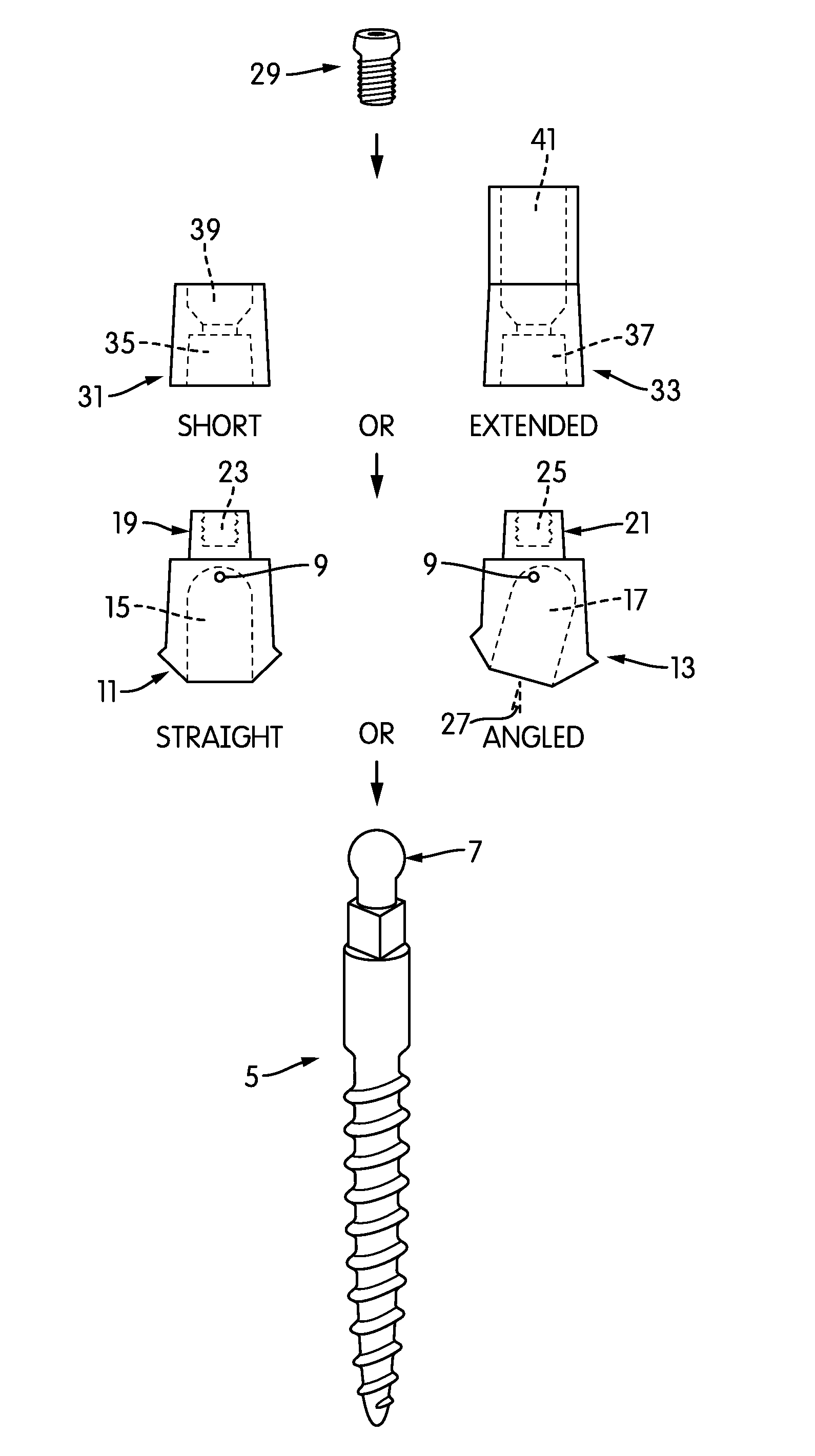
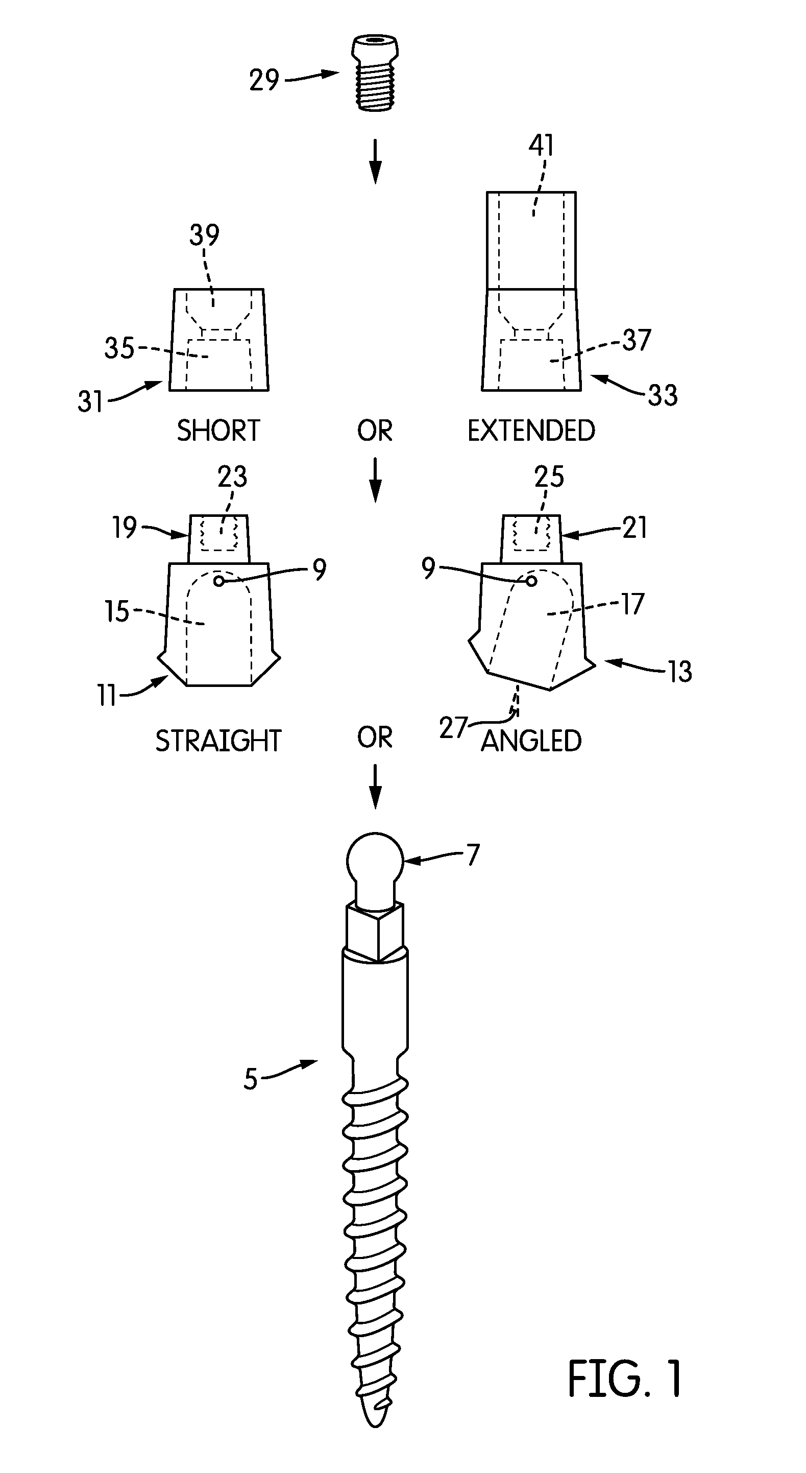
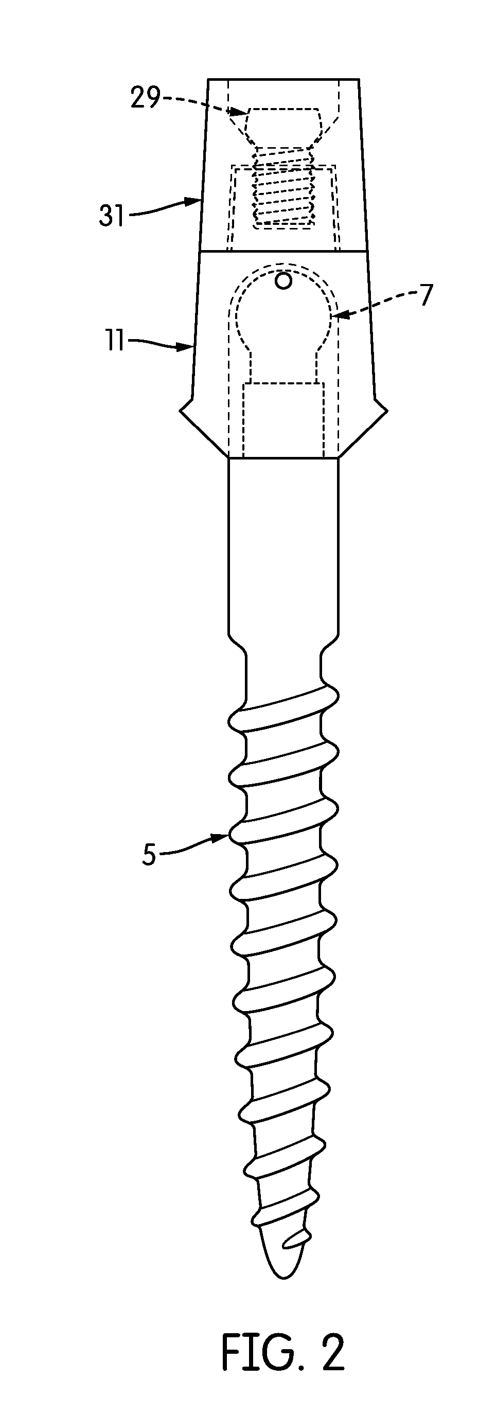
[0013]Through the coping is inserted an occlusal screw, which will screw through the coping, be stopped by the internal constriction, and screw into the coronal outcropping atop the conversion abutment, thus securing the coping and ultimately the prosthesis to the abutment.

Problems solved by technology

However, one-piece dental implants are fabricated with only one fixed head, limiting their use.
At least one drawback to one-piece dental implants is that one is unable to easily place, remove, repair or replace the attached prostheses without damaging the prostheses when permanently cemented, which may cause substantial discomfort and expense to the patient as well as inconvenience for both the patient and the provider.
Existing one-piece dental implants tend to have features that make repairing, replacing or removing fixed prostheses inconvenient.
The problem with one-piece dental implants is that the abutment head is not removable and can only be used in a limited choice of prosthetic treatment options.
The downside to this type of construction is that permanently fixed complete and partial dentures, hybrids, crowns, and bridges cannot be easily retrieved when used with one-piece dental implants.
If a prosthesis becomes damaged or worn or if an implant fails, requiring repair or replacement, one would likely have to damage or destroy the existing prosthesis in order to repair or replace the prosthesis or to have access to treat or remove a failing implant.
However, the one-piece implant described therein does not allow for a screw-based fixation to the implant body and is only used for removable prostheses.

Method used


Image

  • Conversion abutment for dental implants
  • Conversion abutment for dental implants
  • Conversion abutment for dental implants

Examples


Embodiment Construction

[0022]The invention will now be described in greater detail with reference to the accompanying drawings. The drawings, which are incorporated herein and form part of the specification, illustrate various, non-limiting embodiments of the present invention. In the drawings, common reference numbers indicate identical or functionally similar elements.

[0023]Unless defined otherwise, all terms of art, notations and other scientific terms or terminology used herein have the same meaning as is commonly understood by one of ordinary skill in the art to which this disclosure belongs. Many of the techniques and procedures described or referenced herein are well understood and commonly employed using conventional methodology by those skilled in the art. As appropriate, procedures involving the use of commercially available kits and reagents are generally carried out in accordance with manufacturer defined protocols and / or parameters unless otherwise noted. All patents, applications, published ...


PUM


Abstract

A conversion abutment that cements onto one-piece dental implants that convert the one-piece implant use to a retrievable screw retained implant use in retaining complete dentures, hybrids, partial dentures, or fixed screw retained crowns or bridges, allowing the flexibility to retain and remove these restorative prostheses. These conversion abutments can be fabricated as angled conversion abutments to be used with single or multiple implants placed at various angulations. The conversion abutment system consists of three parts: a cementable conversion abutment (straight or angled), a coping (short or extended), and an occlusal screw. The bottom part (or apical portion) of the implant conversion abutment will cement over the one-piece implant in use, while the top (or coronal portion) will allow a screw to fit through a coping into the implant conversion abutment, screwing the prostheses into place.

Description

PRIORITY CLAIM[0001]This application claims the benefit under 35 U.S.C. §119(e) of U.S. Provisional Application No. 61 / 799,669, filed Mar. 15, 2013, the disclosure of which is hereby incorporated by reference in its entirety.FIELD OF THE INVENTION[0002]The present invention relates to conversion abutments that are designed to allow dentists and dental surgeons to place, remove, replace or repair dental prostheses on one-piece dental implants.BACKGROUND OF THE INVENTION[0003]Individuals often find themselves requiring one or more dental prostheses during their lifetime. These prostheses can take the form of complete or partial dentures, crowns, or bridges. They may also take the form of hybrid prostheses which incorporate one or more elements of the aforementioned prostheses. Traditionally, dentistry has provided removable complete and partial dentures, crowns, and fixed bridges to solve the problem of missing teeth. To address issues associated with these traditional approaches, imp...

Claims


Application Information

Patent Timeline
Patent Type & Authority Applications(United States)
IPC IPC(8): A61C8/00A61C13/08
CPCA61C8/0068A61C13/08A61C8/0075A61C8/0053A61C8/0048A61C8/0016
Inventor HARALAMPOPOULOS, HARRY A.HARALAMPOPOULOS, NIKOL H.
Owner HARALAMPOPOULOS HARRY A
Why Eureka
Try Eureka