
Inter Dental Implant

a dental implant and inter-dental technology, applied in dental implants, dental surgery, medical science, etc., can solve the problems of uncomfortable patient waiting period, high cost, and large amount of dentist's tim

Pending Publication Date: 2022-07-14
LOZADA ITALO
View PDF9 Cites 0 Cited by
  • Summary
  • Abstract
  • Description
  • Claims
  • Application Information

AI Technical Summary

Benefits of technology

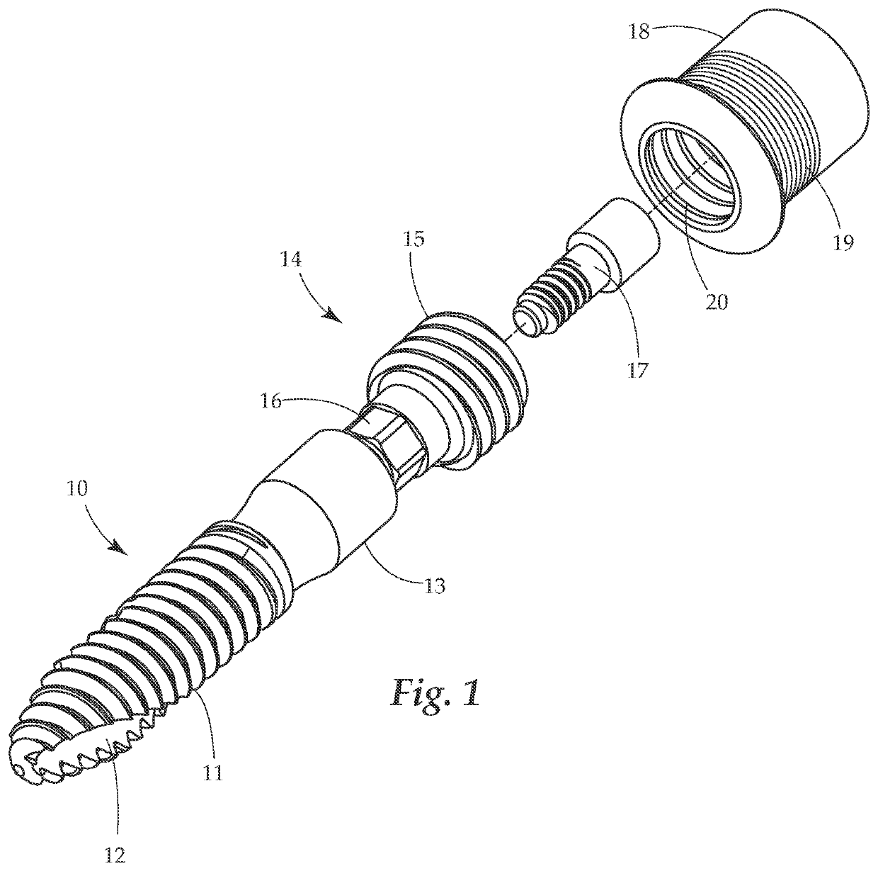
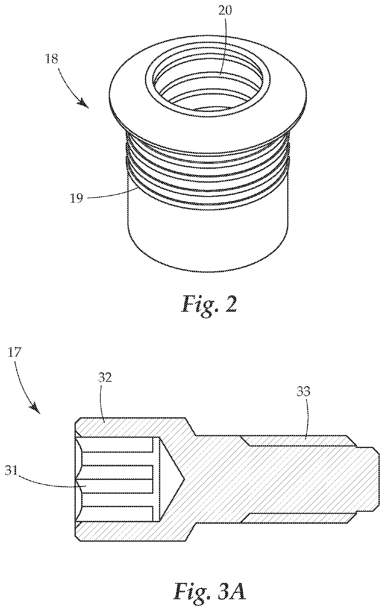
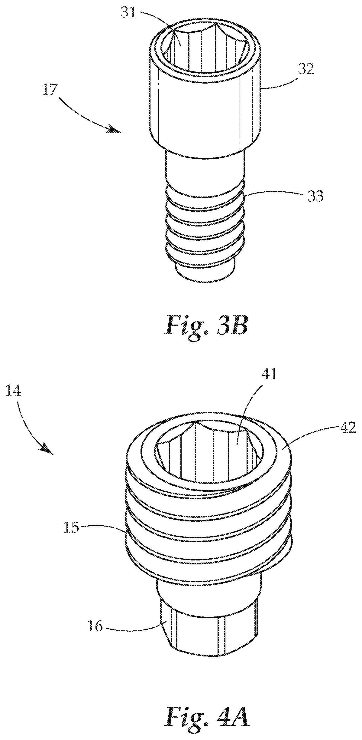
This patent describes a dental prosthesis consisting of an implant and abutment which are connected by a removable screw. The abutment has a central opening through which the screw passes and is secured using threads on the implant and the abutment. The screw can be easily removed by unscrewing it and passing through the abutment's central opening. This design allows for easy replacement and adjustability of the prosthesis.

Problems solved by technology

This process requires a substantial amount of a dentist's time, leading to higher costs.
Further, the waiting period after the screw is implanted is uncomfortable and difficult for the patient.
Further still, the bone target for screw installation, which will be drilled, is often not uniform, and is difficult to estimate.
As such, the drilling may easily be off, causing a misaligned screw, or worse.
Unguided drilling creates a number of additional difficulties such as maintaining proper drill orientation throughout the entire drilling process.
Failure to maintain proper orientation through the entire drill cycle can cause unwanted widening of the drilled hole as well as a non-straight and non-uniform hole.
Improper orientation can also cause damage to the adjacent anatomical structures such as perforation of the sinus cavity, puncture or close placement of the implant to the nerve canal, unwanted proximity to the roots of adjacent teeth, perforation of the buccal or lingual alveolar plate of the area in question, among others issues.

Method used


Image

  • Inter Dental Implant
  • Inter Dental Implant
  • Inter Dental Implant

Examples


Embodiment Construction

[0020]The detailed description set forth below in connection with the appended drawings is intended as a description of presently preferred embodiments of the invention and does not represent the only forms in which the present invention may be constructed and / or utilized. The description sets forth the functions and the sequence of steps for constructing and operating the invention in connection with the illustrated embodiments.

[0021]Generally, the present invention concerns a dental prosthesis which may, in many embodiments, be installed concurrently with an implant (bone screw) to support and anchor the crown / denture / partial denture. The dental prosthesis system disclosed herein, in some embodiments also takes advantage of a crown mounted to a ti-base which defines a passageway through it, this passageway is operable to guide the placement of the implant by directing and limiting movement from an intended path of placement into the patient. The passageway may guide a drill bit wh...


PUM


Abstract

A multi-piece dental prosthesis system is provided. The system includes an implant which can be implanted into a bone of the patient, an abutment removably connected to the implant by a prosthetic screw, and a ti-base removably connected to the abutment. The system may be used to hold a crown, denture, or partial denture in place.

Description

BACKGROUND OF THE INVENTIONField of the Invention[0001]The present invention relates generally to inner dental implant systems. Specifically, the present invention relates to a multi-piece dental prosthesis system.Description of Related Art[0002]Generally, the installation of a dental prosthesis replicating a tooth is performed in two steps. The first step is the installation of a bone screw (“implant”) into a bone of a patient. This involves drilling a hole, and then setting a screw. This screw must then set for a period of time to allow the patient's body to adapt and accept the screw, and allow new bone growth in and around the screw. Only after this time period has elapsed can a replica tooth prosthesis (commonly called a “crown”) be installed by connecting it to this now secure screw. Usually this connection is via an adhesive. This process requires a substantial amount of a dentist's time, leading to higher costs. Further, the waiting period after the screw is implanted is unc...

Claims


Application Information

Patent Timeline
IPC IPC(8): A61C8/00
CPCA61C8/0054A61C8/0074A61C8/0069A61C8/0068A61C8/006A61C8/0022A61C8/0048
Inventor LOZADA, ITALO
Owner LOZADA ITALO
Learn More