Medical connector

a technology of medical connectors and connectors, applied in medical science, packaging, diagnostics, etc., can solve the problems of limiting the opportunities for pathogens to enter the system, inherent risk of blood stream infections,

Active Publication Date: 2014-09-18
ICU MEDICAL INC
View PDF6 Cites 67 Cited by
  • Summary
  • Abstract
  • Description
  • Claims
  • Application Information

AI Technical Summary

Benefits of technology

[0038]In various embodiments, a needleless medical connector can include a connector housing comprising an inner cavity and a compressible seal positioned at least partially within the inner cavity of the connector housing, the compressible seal having: a body wall that defines an interior space; an upper section, a lower section, and a shoulder between the upper section and the lower section; and a slit on a top of the seal that extends through the top of the seal and into the interior space. The compressible seal can have a first position in which the slit is generally closed to prevent fluid from passing through the slit and a second position in which the compressible seal has been pushed downward by a medical implement and the slit is open to allow fluid to pass through the slit and into the interior space of the compressible seal. At least a portion of the upper section of the compressible seal can have an outer diameter that is greater than an inner diameter of the inner cavity that is aligned with the portion of the upper section when the compressible seal is in the first position, thereby minimizing fluid that can pass between the portion of the upper section of the compressible seal and the connector housing. Such portions of the upper section of the compressible seal can also be configured to remain in contact with walls of the inner cavity as the seal moves from the second position to the first position to ensure that fluid that may be on the walls of the inner cavity, even if outside of the typical fluid path, is directed out of the inner cavity through an upper opening to the inner cavity.

Problems solved by technology

Because such flow lines provide access to a patient's blood stream, they inherently generate risks of blood stream infections, as pathogens can make their way into the fluid flow lines at different access points.
Generally, risks of infection or other complications can be minimized by limiting the number of times that flow lines need to be established, which limits the opportunities for pathogens to enter the system.
Blood can accumulate in ports when they are not in use, and the ports can clot and cause problems in the line, requiring it to be reestablished.

Method used


Image

  • Medical connector
  • Medical connector
  • Medical connector

Examples


Embodiment Construction

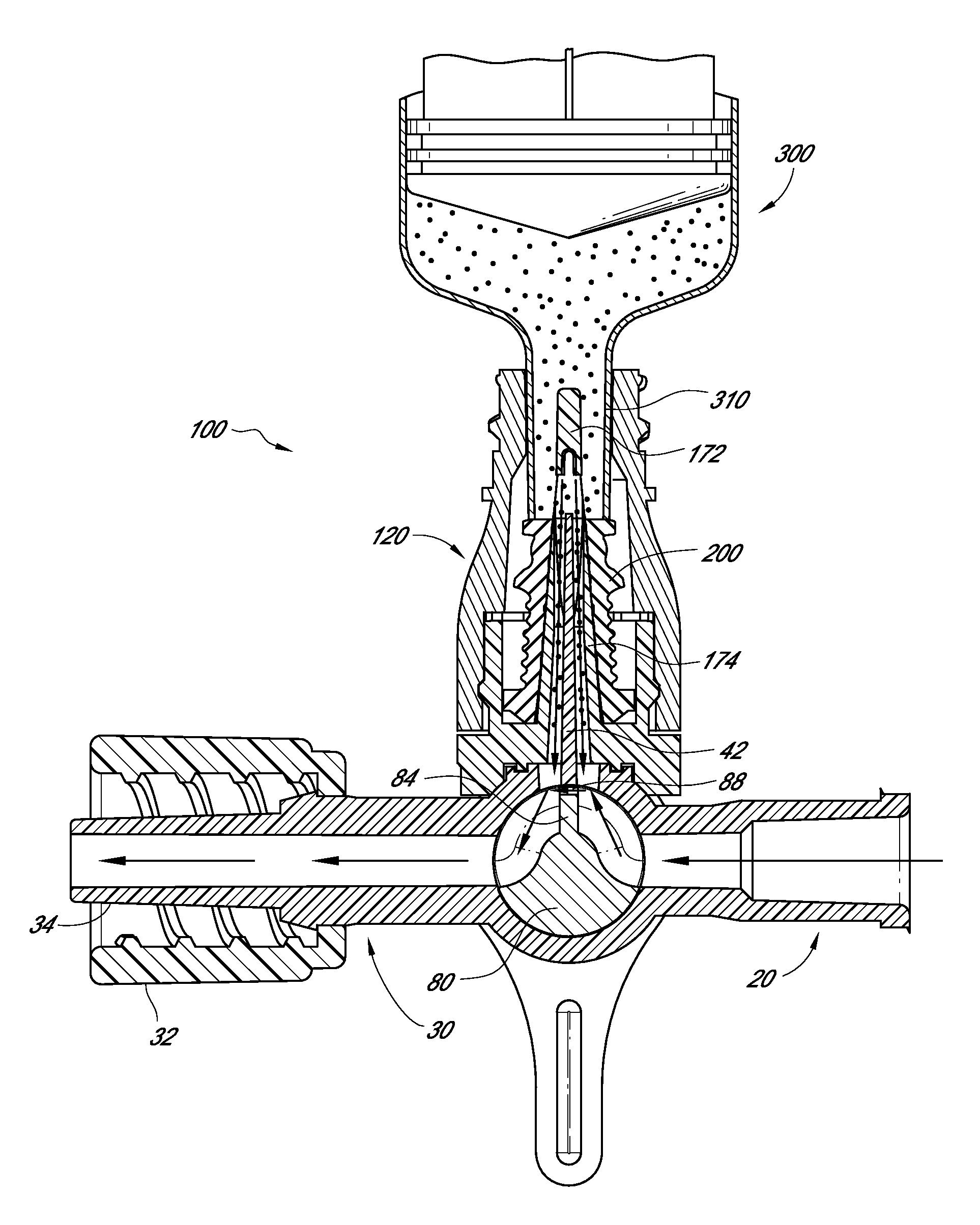
[0114]With reference to the attached figures, certain embodiments and examples of fluid flow systems and medical connectors will now be described. Various embodiments described herein are with reference to a three-port stopcock, but they are not so limited. In some aspects, they can be applied to four-port stopcocks, other branched connectors including y-site connectors, or any device that has a flow of fluid and a component such that it can be beneficial to make sure that fluid flushes through the component. Various embodiments relating to a needleless access port can also be applied to any access port within or at the end of a fluid line, for example, a closed female luer connector with an open or closed male luer opposite end. As used herein, the term “fluid” refers to either gases or liquids.

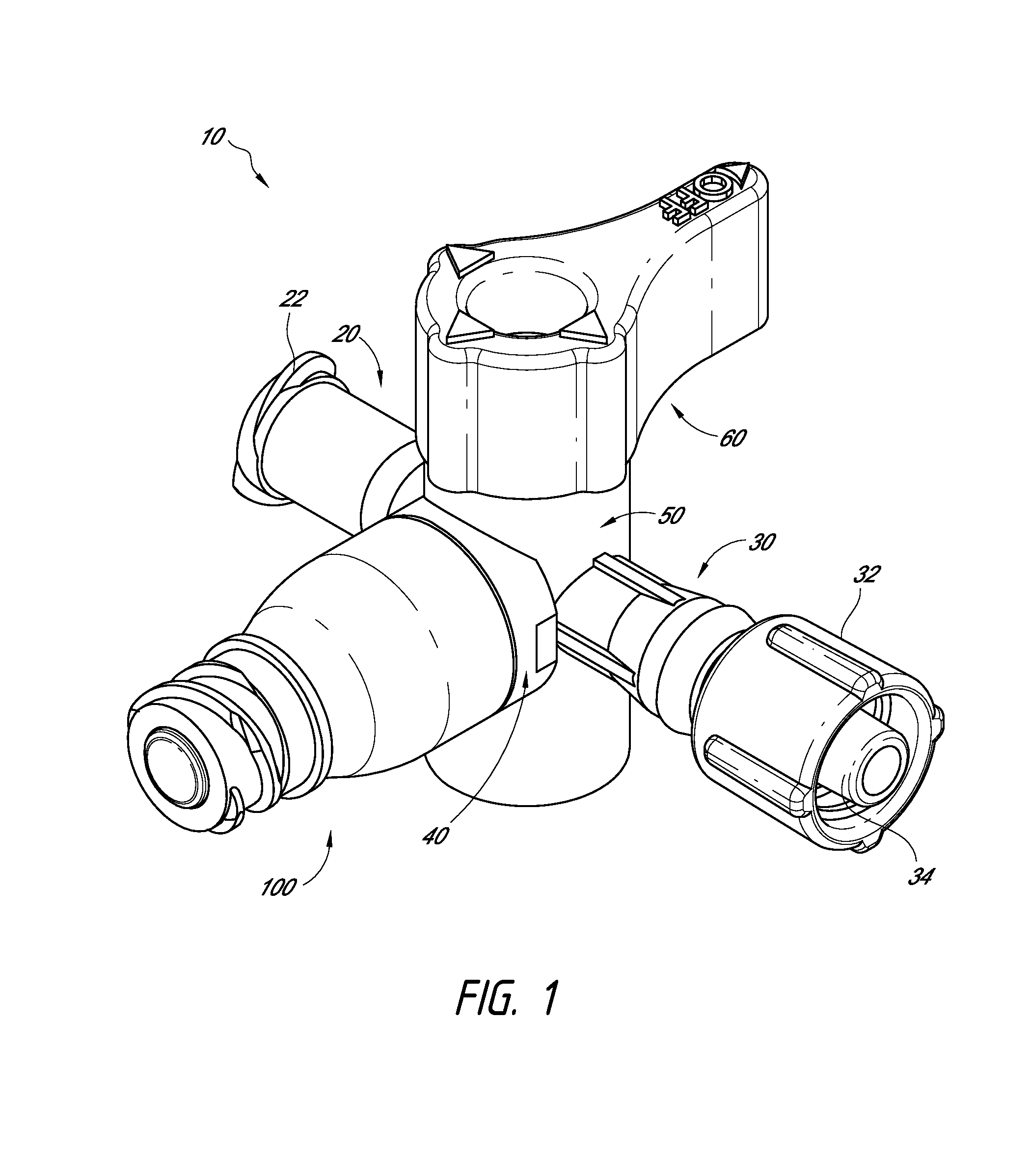
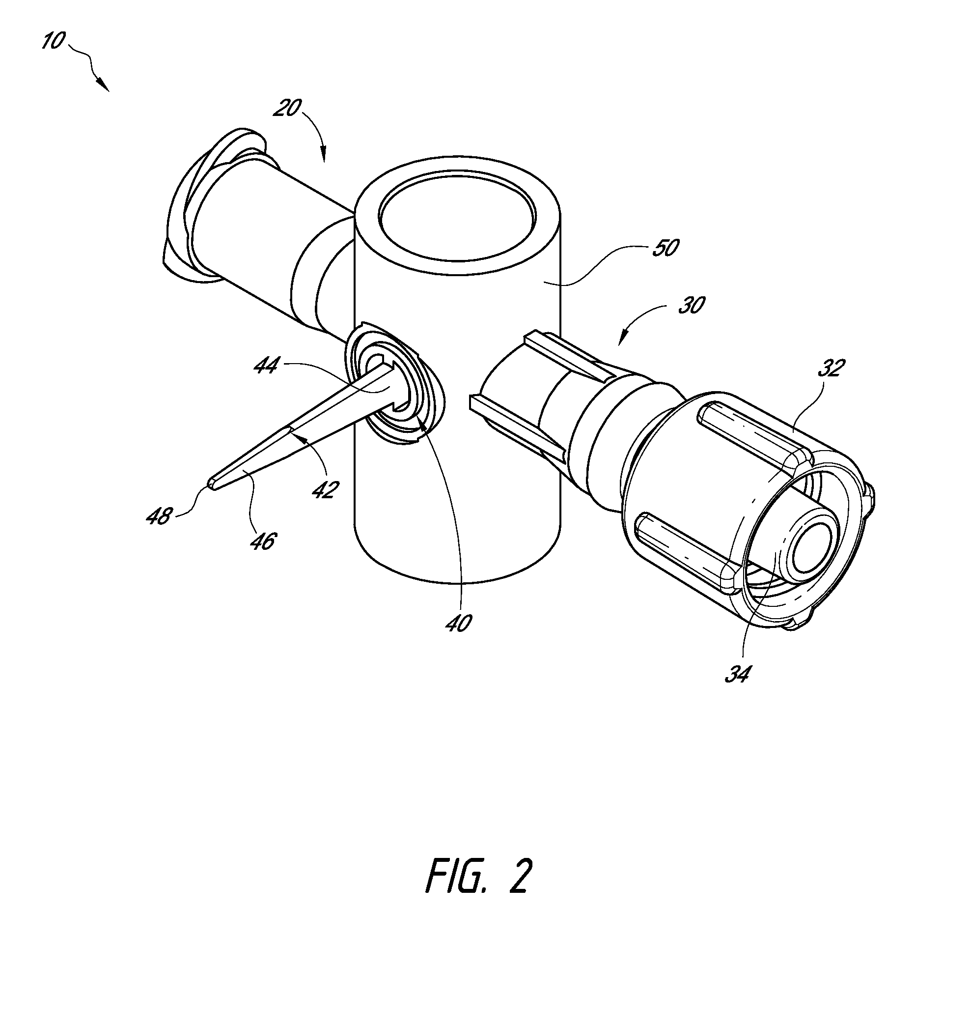
[0115]FIG. 1 illustrates one embodiment of a stopcock 10 that can be used within a fluid flow line. The stopcock can include a first port 20, a second port 30 opposite the first port, and a ...


PUM


Abstract

A medical connector for use in a fluid pathway. A valve member with sealing rings helps preclude undesired accumulation of fluid within the connector. A branched connector includes a fluid diverter extending away from a port of the branched connector. The fluid diverter is configured to divert fluid flowing through the branched connector and into a medical connector attached thereto, flushing a distal portion of the medical connector.

Description

CROSS-REFERENCE TO RELATED APPLICATIONS[0001]Any and all applications for which a foreign or domestic priority claim is identified in the Application Data Sheet as filed with the present application, are hereby incorporated by reference under 37 CFR 1.57. The present application claims the benefit of U.S. Provisional Patent Application No. 61 / 793,511, filed Mar. 15, 2013, and entitled “MEDICAL CONNECTOR”; U.S. Provisional Patent Application No. 61 / 884,913, filed Sep. 30, 2013, and entitled “MEDICAL CONNECTOR”; and U.S. Provisional Patent Application No. 61 / 914,680, filed Dec. 11, 2013, and entitled “MEDICAL CONNECTOR,” the entire disclosure of each being hereby incorporated by reference herein and made a part of this disclosure.BACKGROUND OF THE INVENTION[0002]1. Field of the Disclosure[0003]The present disclosure relates in general to the field of medical connectors, and in particular to selectively sealed medical connectors.[0004]2. Description of the Related Art[0005]A variety of...

Claims


Application Information

Patent Timeline
Patent Type & Authority Applications(United States)
IPC IPC(8): A61M39/22A61B5/15
CPCA61B5/150992A61M39/225A61B5/15003A61B5/150221A61M39/223
Inventor NELSON, DAVIDFANGROW, THOMAS F.
Owner ICU MEDICAL INC
Why Eureka
Try Eureka