Shift control apparatus for vehicle

a technology for shifting control and vehicle, which is applied in mechanical equipment, transportation and packaging, propulsion parts, etc., can solve the problems of increasing aggravated loss of power balance, and increasing the risk of shifting shock generation, so as to reduce the risk of generation of shifting shock of the step-variable transmission portion

Active Publication Date: 2018-06-07
TOYOTA JIDOSHA KK
View PDF0 Cites 1 Cited by
  • Summary
  • Abstract
  • Description
  • Claims
  • Application Information

AI Technical Summary

Benefits of technology

[0005]The present invention was made in view of the background art described above. It is therefore an object of the present invention to provide a shift control apparatus for a vehicle provided with a drive power source, and a step-variable transmission portion having a plurality of hydraulically operated coupling devices, which shift control apparatus is configured to reduce a shifting shock of the step-variable transmission portion even when the vehicle is switched from its non-driving state to its driving state during a shift-down action of the step-variable transmission portion initiated in the non-driving state of the vehicle.

Problems solved by technology

If, for example, the mode of hydraulic control is switched to the vehicle-driving mode after the shift-down action in the non-driving state has sufficiently progressed (after a moment of initiation of an inertia phase of the shift-down action, for instance), however, it is difficult to implement a speed control of the step-variable transmission portion during the inertia phase, so that an inertial power of the step-variable transmission portion varies, with a result of loss of a power balance among an engine power, the inertial power and a power (vehicle drive power) transmitted through the coupling devices, giving rise to a risk of generation of a shifting shock of the step-variable transmission portion.
Where the drive power source provided in the vehicle includes an electric motor, the shift-down action of the step-variable transmission portion is controlled by taking account of a power balance involving a battery power, in addition to the above-indicated engine power, inertial power and vehicle drive power, so that where the battery power is limited upon switching of the vehicle from the non-driving state to the driving state in the process of the shift-down action, the loss of the power balance is further aggravated, and the risk of generation of the shifting shock is increased.

Method used


Image

  • Shift control apparatus for vehicle
  • Shift control apparatus for vehicle
  • Shift control apparatus for vehicle

Examples


embodiments

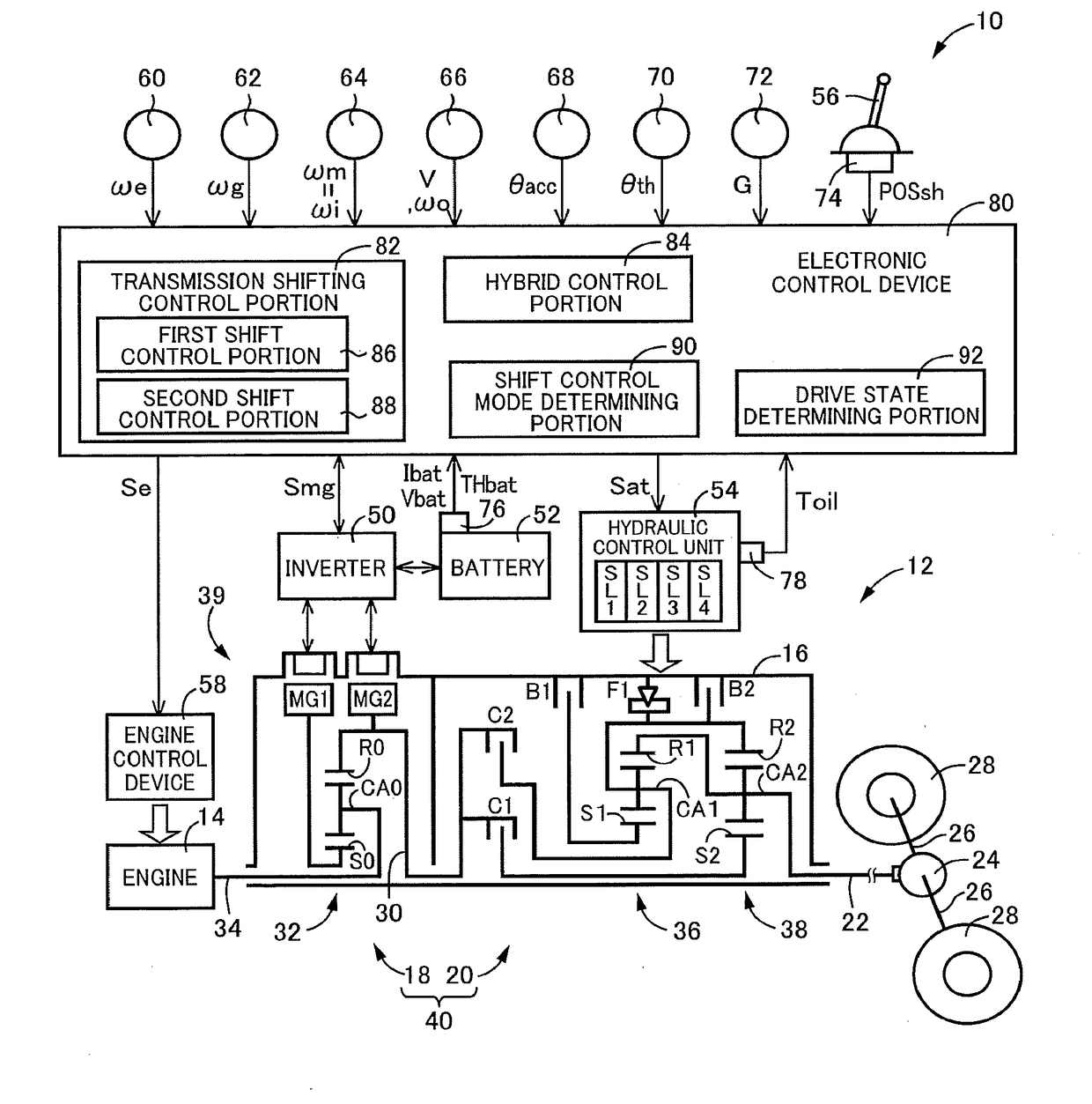
[0028]Reference is first made to FIG. 1, which is the schematic view showing an arrangement of a drive system 12 of a vehicle 10 to be controlled by a shift control apparatus according to the present invention, and major portions of the shift control apparatus to perform various controls of the vehicle 10. As shown in FIG. 1, the vehicular drive system 12 is provided with an engine 14 functioning as a drive power source, an electrically controlled continuously variable transmission portion 18 (hereinafter referred to as “continuously variable transmission portion 18”) connected directly or indirectly via a damper (not shown) or any other device to the engine 14, and a mechanically operated step-variable transmission portion 20 (hereinafter referred to as “step-variable transmission portion 20”) connected to an output rotary member of the continuously variable transmission portion 18. The continuously variable transmission portion 18 and the step-variable transmission portion 20 are ...


PUM


Abstract

A shift control apparatus (80) for a vehicle (10; 100) provided with a drive power source (39; MG), and a step-variable transmission portion (20; 110) including a plurality of hydraulically operated coupling devices (CB), the shift control apparatus controlling the step-variable transmission portion to implement a shifting action with an engaging action of the engaging-side coupling device and a releasing action of the releasing-side coupling device, and including a shift control portion (82) to control a shift-down action of the step-variable transmission portion in a predetermined mode of hydraulic control of the engaging-side and releasing-side coupling devices, wherein the shift control portion controls the engaging-side and releasing-side coupling devices in a non-vehicle-driving control mode during the shift-down action of the step-variable transmission portion in a non-driving state of the vehicle, the shift control portion switching the mode of hydraulic control from the non-vehicle-driving control mode to a vehicle-driving control mode where the vehicle is switched from the non-driving state to a driving state within a predetermined length of time after a moment of initiation of the shift-down action, and maintaining the non-vehicle-driving control mode where the vehicle is switched to the driving state after the predetermined length of time has passed, while limiting a torque of the drive power source during the shift-down action to a predetermined value in the non-vehicle-driving control mode.

Description

[0001]This application claims priority from Japanese Patent Application No. 2016-236255 filed on Dec. 5, 2016, the disclosure of which is herein incorporated by reference in its entirety.FIELD OF THE INVENTION[0002]The present invention relates to a shift control apparatus for a vehicle provided with a drive power source and a step-variable transmission portion.BACKGROUND OF THE INVENTION[0003]There is known a shift control apparatus for a vehicle provided with a drive power source, and a step-variable transmission portion disposed in a power transmitting path between the drive power source and drive wheels and having a plurality of hydraulically operated coupling devices, which shift control apparatus controls the step-variable transmission portion to implement a shifting action with an engaging action of the engaging-side coupling device to be brought into its engaged state to implement the shifting action, and a releasing action of the releasing-side coupling device to be brought...

Claims


Application Information

Patent Timeline
Patent Type & Authority Applications(United States)
IPC IPC(8): F16H61/06F16H61/08F16H61/686B60K6/547
CPCF16H61/061F16H61/08F16H61/686B60K6/547F16H2061/0459B60K2702/02B60W20/30F16H61/06B60K6/445F16H59/18F16H61/0437B60W20/15B60K6/365B60W30/19B60W10/08B60W10/06B60W10/115B60W2540/10B60W2510/1005Y02T10/62
Inventor KOBAYASHI, NOBUFUSAYOSHIKAWA, MASATOKUMAZAKI, KENTA
Owner TOYOTA JIDOSHA KK
Why Eureka
Try Eureka