Vessels, contact surfaces, and coating and inspection apparatus and methods

a technology of contact surfaces and inspection apparatus, which is applied in the direction of mechanical equipment, coatings, syringes, etc., can solve the problems of phlebotomists using tubes that fail to draw sufficient blood, and achieve the effect of reducing the transmission of fluid

Active Publication Date: 2012-10-04
SI02 MEDICAL PRODS
View PDF11 Cites 117 Cited by
  • Summary
  • Abstract
  • Description
  • Claims
  • Application Information

AI Technical Summary

Benefits of technology

[0016]Another aspect of the invention is a medical device comprising a substrate defining a contact surface as defined above and a barrier l

Problems solved by technology

A defective tube is likely to cause the phlebotomi

Method used


Image

  • Vessels, contact surfaces, and coating and inspection apparatus and methods
  • Vessels, contact surfaces, and coating and inspection apparatus and methods
  • Vessels, contact surfaces, and coating and inspection apparatus and methods

Examples


working examples

Basic Protocols for Forming and Coating Tubes and Syringe Barrels

[0600]The vessels tested in the subsequent working examples were formed and coated according to the exemplary protocols set out in U.S. Pat. No. 7,985,188 as incorporated by reference, except as otherwise indicated in individual examples. Whenever parameter values were changed in comparison to these typical values, this will be indicated in the subsequent working examples. The same applies to the type and composition of the process gas.

example 1

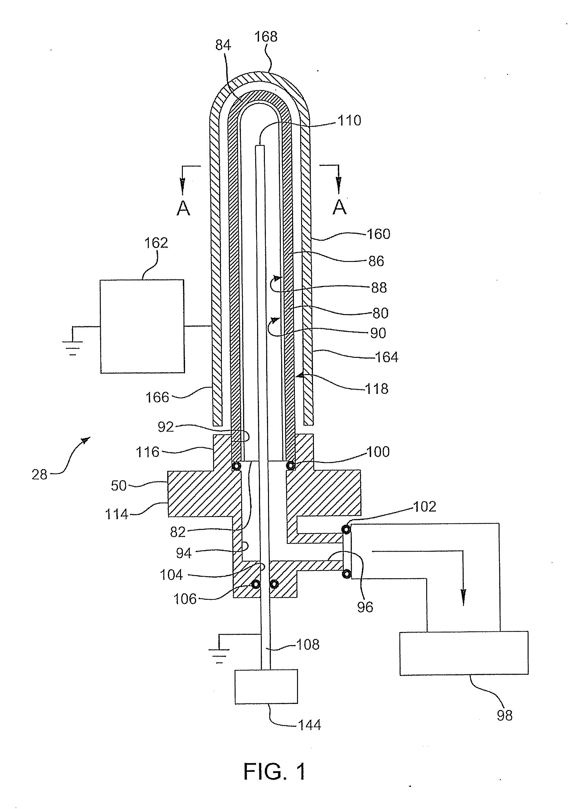
[0601]V. In the following test, hexamethyldisiloxane (HMDSO) was used as the organosilicon (“O—Si”) feed to PECVD apparatus of FIG. 1 to apply an SiOx coating on the internal contact surface of a cyclic olefin copolymer (COC) tube as described in the Protocol for Forming COC Tube. The deposition conditions are summarized in the Protocol for Coating Tube Interior with SiOx and Table 1. The control was the same type of tube to which no barrier coating was applied. The coated and uncoated tubes were then tested for their oxygen transmission rate (OTR) and their water vapor transmission rate (WVTR).

[0602]V. Referring to Table 1, the uncoated COC tube had an OTR of 0.215 cc / tube / day. Tubes A and B subjected to PECVD for 14 seconds had an average OTR of 0.0235 cc / tube / day. These results show that the SiOx coating provided an oxygen transmission BIF over the uncoated tube of 9.1. In other words, the SiOx barrier coating reduced the oxygen transmission through the tube to less than one nint...

example 2

[0605]V. A series of PET tubes, made according to the Protocol for Forming PET Tube, were coated with SiOx according to the Protocol for Coating Tube Interior with SiOx under the conditions reported in Table 2. Controls were made according to the Protocol for Forming PET Tube, but left uncoated. OTR and WVTR samples of the tubes were prepared by epoxy-sealing the open end of each tube to an aluminum adaptor.

[0606]V. In a separate test, using the same type of coated PET tubes, mechanical scratches of various lengths were induced with a steel needle through the interior coating, and the OTR BIF was tested. Controls were either left uncoated or were the same type of coated tube without an induced scratch. The OTR BIF, while diminished, was still improved over uncoated tubes (Table 2A).

[0607]V. Tubes were tested for OTR as follows. Each sample / adaptor assembly was fitted onto a MOCON® Oxtran 2 / 21 Oxygen Permeability Instrument. Samples were allowed to equilibrate to transmission rate st...


PUM

PropertyMeasurementUnit
Fractionaaaaaaaaaa
Fractionaaaaaaaaaa
Nanoscale particle sizeaaaaaaaaaa

Abstract

Methods for processing a contact surface, for example to provide a gas barrier or lubricity or to modify the wetting properties on a medical device, are disclosed. First and second PECVD or other contact surface processing stations or devices and a contact surface holder comprising a contact surface port are provided. An opening of the contact surface can be seated on the contact surface port. The interior contact surface of the seated contact surface can be processed via the contact surface port by the first and second processing stations or devices. contact surface barrier, lubricity and hydrophobic coatings and coated contact surfaces, for example syringes and medical sample collection tubes are disclosed. A contact surface processing system and contact surface inspection apparatus and methods are also disclosed.

Description

CROSS REFERENCE TO RELATED APPLICATIONS[0001]This application claims the priority of U.S. Ser. No. 61 / 471,056, filed Apr. 1, 2011, which is incorporated here by reference in its entirety.[0002]The following patent applications, publications, and patents are incorporated here by reference in their entirety.Application No.Filing DatePublication No.61 / 177,984May 13, 200961 / 222,727Jul. 2, 200961 / 213,904Jul. 24, 200961 / 234,505Aug. 17, 200961 / 261,321Nov. 14, 200961 / 263,275Nov. 20, 200961 / 263,289Nov. 20, 200961 / 285,813Dec. 11, 200961 / 298,159Jan. 25, 201061 / 299,888Jan. 29, 201061 / 318,197Mar. 26, 201061 / 333,625May 11, 201012 / 779,077May 12, 2010U.S. Pat. No. 7,985,188EP10162755.2May 12, 2010EP2253735A2EP10162760.2May 12, 2010EP2251454A2EP10162757.8May 12, 2010EP2251453A2EP10162756.0May 12, 2010EP2251452A2EP10162758.6May 12, 2010EP2251671A2EP10162761.0May 12, 2010EP2251455A2PCT / US10 / 34568May 12, 2010WO 2010 / 132579PCT / US10 / 34571May 12, 2010WO 2010 / 132581PCT / US10 / 34576May 12, 2010WO 2010 / 132584P...

Claims


Application Information

Patent Timeline
IPC IPC(8): F16C33/20
CPCA61M5/3129C23C16/0272C23C16/045A61M2005/3131C23C16/36A61M2005/3104C23C16/30
Inventor FELTS, JOHNFISK, THOMASABRAMS, ROBERTFERGUSON, JOHNFREEDMAN, JONATHANPANGBORN, ROBERTSAGONA, PETER
Owner SI02 MEDICAL PRODS
Why Eureka
Try Eureka