Backpressure mechanism for switching fabric

a backpressure mechanism and fabric technology, applied in data switching networks, instruments, frequency-division multiplexes, etc., can solve the problems of counterintuitive use of multi-stage fabric for packet-based switching, reducing control signaling even further, etc., to achieve sufficient internal memory, simplify packet scheduling problems, and reduce complexity. the effect of the packet transmission control mechanism

Inactive Publication Date: 2008-09-04
INTEL CORP
View PDF46 Cites 128 Cited by
  • Summary
  • Abstract
  • Description
  • Claims
  • Application Information

AI Technical Summary

Benefits of technology

[0014]In an aspect of the invention, roughly described, the packet scheduling problem is simplified enormously by removing the requirement that the scheduling algorithm coordinate among all the input ports, and removing the requirement that it consider the constraints of any of the output ports. Instead, the input queues are divided into small groups (each group perhaps located on a different input module), and a separate, independent queue scheduler is provided to serve each group. Each queue scheduler can be ignorant of the decisions being made by other schedulers responsible for serving other input queues, because the problem of more than one uncoordinated input sending a packet to the same output port is handled by including a memory between the inputs and each given output that has enough writing bandwidth to be able to accept packets from all the input port schedulers at the same time. In one embodiment, a multistage switching fabric is used instead of a crossbar fabric. In another embodiment, a single stage switching fabric is used with sufficiently fast internal memory. By removing the requirement that the scheduler responsible for one group of input queues coordinate with the schedulers responsible for all other groups of input queues, the requirement for control signaling among the input ports also can be removed. Thus as the system grows to accommodate more input ports, the packet transmission control mechanism need not increase significantly in complexity. Instead, the function can be divided among more queue schedulers, each no more complex than the basic queue scheduler. And when the system grows to the point of requiring input ports to be distributed among a number of input modules, the packet transmission control function no longer restricts this growth because the queue schedulers, too, can be distributed among the same number of input modules without incurring additional costs for communicating control signaling among the input ports.
[0015]Each queue scheduler is also ignorant of the instantaneous state of the output ports; the scheduler makes its decisions based only (with one exception) on the local state of its input queues. Output port control is handled by a separate set of flow monitors and supervisors which police output port bandwidth utilization by each of the individual input threads and assert backpressure toward the input port queue scheduler that is responsible for scheduling packets for any thread that is exceeding its bandwidth allocation. The one exception above with respect to the local nature of the factors on which a queue scheduler makes its decisions, is that the queue scheduling algorithm is modified to the extent that input queues for which backpressure is asserted are ineligible for scheduling. By policing output port usage and controlling bandwidth allocations through backpressure (or other feedback) rather than affirmatively considering all output port states in each scheduling decision, the need for control signaling between the output ports and the schedulers, too, is vastly reduced. In addition, the policing can occur on a much slower time scale than the per-time-slot output port utilization coordination used by conventional crossbar schedulers, thereby reducing the control signaling even further.
[0016]Accordingly, the aspects of the invention described above nearly eliminate the centralized scheduler as a bottleneck on the growth of packet-based switching fabrics to accommodate greater numbers of input and output ports.

Problems solved by technology

In addition, the policing can occur on a much slower time scale than the per-time-slot output port utilization coordination used by conventional crossbar schedulers, thereby reducing the control signaling even further.
The use of a multistage fabric for packet-based switching may be counterintuitive because in the past, such fabrics have been used mostly for circuit-based switching applications.

Method used


Image

  • Backpressure mechanism for switching fabric
  • Backpressure mechanism for switching fabric
  • Backpressure mechanism for switching fabric

Examples


implementation example — single cashmere embodiment

Implementation Example—Single Cashmere Embodiment

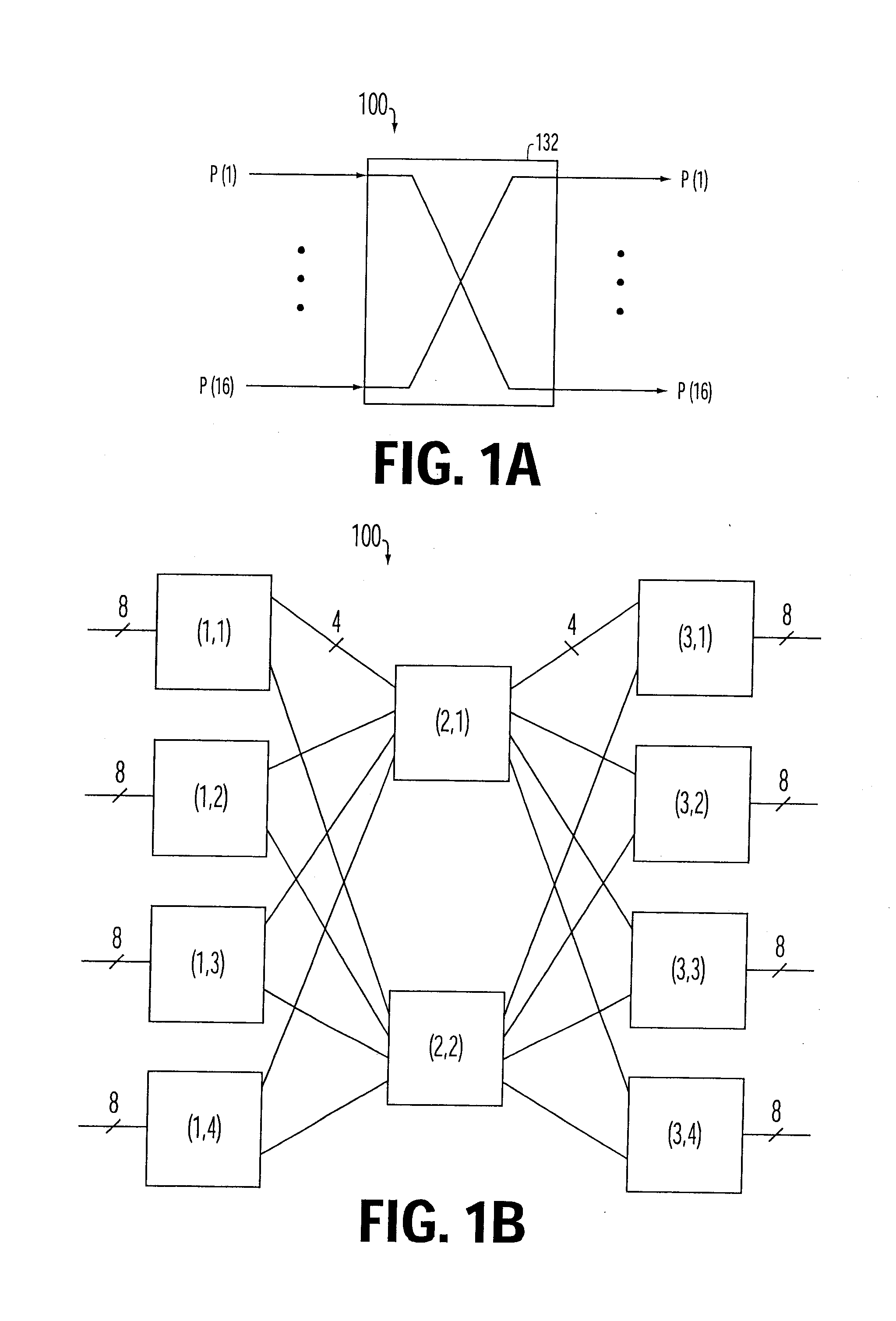
[0133]Implementation details of a single Cashmere embodiment will now be described. In this embodiment, the fabric supports 16 bidirectional interfaces, 3 unicast classes (TS_U, BP_U and BE_U), and 3 multicast classes (TS_M, BP_M and BE_M).

Sharing between Classes, Unicast, and Multicast

[0134]The leaky bucket controller called Data Flow Monitor (DFM) in the device is responsible for monitoring the traffic bound to different outputs. The DFM maintains a set called Output Bucket Set (OBS) of Leaky Buckets (LBs) for each output port. Each set contains 16 Thread LBs (T-LBs) for Best Effort traffic, 16 T-LBs for Bandwidth Provisioned traffic, a single T-LB for all TS traffic, a single T-LB for all BE multicast, a single T-LB for BP multicast traffic, and a single T-LB for all TS multicast traffic bound for the corresponding output port. Each of the T-LBs are filled in proportion to the traffic of each type bound for the corresponding output...


PUM


Abstract

Roughly described, a packet switching fabric contains a separate queue scheduler for each combination of an input module and a fabric output port. The schedulers may also be specific to a single class of service. Each queue scheduler schedules its packets without regard to state of other input queues and without regard to packets destined for other output ports. In an aspect, the fabric manages per-flow bandwidth utilization of output port bandwidth capacity by monitoring the same and asserting backpressure toward the queue scheduler for any thread that is exceeding its bandwidth allocation. In another aspect, a switching fabric uses leaky buckets to apply backpressure in response to overutilization of downstream port capacity by particular subflows. In another aspect, a switching fabric includes a cascaded backpressure scheme.

Description

CROSS-REFERENCES[0001]This application is a continuation of U.S. patent application Ser. No. 10 / 358,678, filed on 02 / 05 / 03, which itself claims the benefit of U.S. Provisional Application No. 60 / 362,144, filed Mar. 6, 2002, both of which are incorporated herein by reference in their entirety.BACKGROUND[0002]1. Field of the Invention[0003]The invention relates to switching fabrics, and more particularly to a flow control method and apparatus for fairly allocating the bandwidth capacity of the fabric to multiple input flows.[0004]2. References[0005]The following U.S. patents are incorporated herein by reference in their entirety: U.S. Pat. Nos. 6,388,992; 5,903,735; 5,280,470; 5,930,234; and 5,455,826.[0006]3. Description of Related Art[0007]A switch fabric for a data network is a device that allows data from any of several input ports to be communicated switchably to any of several output ports. Early data networks were based on circuit switching, in which fixed routes were establish...

Claims


Application Information

Patent Timeline
Patent Type & Authority Applications(United States)
IPC IPC(8): H04L12/28
CPCH04L49/1515H04L49/201H04L49/205H04L49/25H04Q3/68H04L49/3018H04L49/3027H04L49/3072H04L49/254
Inventor MUSACCHIO, JOHN T.WALRAND, JEANMYERS, ROY T.PAREKH, SHYAM P.MO, JEONGHOONAGARWAL, GAURAV
Owner INTEL CORP
Why Eureka
Try Eureka