Fluid Flow Control Device with Retractable Cannula

a flow control device and cannula technology, applied in the direction of catheters, instruments, infusion needles, etc., can solve the problems of iv tube rearward movement, cap or cover that must be replaced over the cannula, and unsatisfactory solutions, so as to prevent accidental needle sticks, avoid accidental needle sticks, and prevent reuse of the device

Inactive Publication Date: 2009-12-10
RETRACTABLE TECH INC
View PDF15 Cites 136 Cited by
  • Summary
  • Abstract
  • Description
  • Claims
  • Application Information

AI Technical Summary

Benefits of technology

[0007]The apparatus of the invention comprises a device that is particularly well suited for use in the medical field, but is not necessarily limited to medical use. According to one preferred embodiment of the invention, a medical device is disclosed that has a cannula and can be configured and used for fluid injection, infusion or extraction. Depending upon its configuration, the subject device can be used, for example: As part of an infusion set or as a collection device for venous or arterial blood; for other body fluids such as spinal fluid, cerebral fluid, amniotic fluid, and the like that are well known to healthcare workers; or for solid matter contained in suspensions or slurries such as, for example, medications, lipids or bone marrow. When the device is used for infusing fluids or medication, the fluid source can be, for example, an IV drip bag or a syringe. When the device is used for collecting blood, the fluid receptacle can be, for example, a blood collection bag, an evacuated tube or a syringe. When the device is attached to a fluid flow line, it can also be used as a clamp. Prior to retraction of the cannula, the device prevents fluid leakage into or out of the fluid flow path. The cannula is typically a needle having a front end that is beveled to facilitate insertion into tissue or into another medical device such as a port.
[0011]According to a preferred embodiment of the invention, a device is disclosed that preferably comprises a housing; a cannula projecting forwardly from the housing; a connector useful for attaching the device to a fluid source or receptacle; a fluid flow path establishing fluid communication between the cannula and the connector; a retraction mechanism biasing the cannula away from its projecting position; and an actuator supported by the housing and configured to modify the fluid flow path so as to terminate fluid flow through the device, seal off the fluid flow path, and release the retraction mechanism to retract the cannula into the housing. Laterally extending finger grips and / or stabilization wings with finger pads are desirably provided to facilitate manipulation of the device by a user, to resist rolling of the device on an underlying surface, and to provide surfaces that can be secured to a patient during use.
[0012]According to another preferred embodiment of the invention, the actuator portion of the device comprises two elongate, most preferably cylindrical, cavities, including one cavity that defines a portion of the fluid flow path and another that is a retraction cavity configured to receive a portion of the retraction mechanism and cannula following retraction. The retraction mechanism preferably comprises a holder for the needle or cannula, and a biasing member such as a compression spring. The actuator is preferably movable by the user from a first position to a second position to modify the fluid flow path by interrupting, displacing, redirecting or reconfiguring at least part of the path, thereby cutting off fluid flow along the original flow path through the device. At least part of the actuator is either slidably mounted or rotatably, most preferably pivotally, connected inside the housing. Movement of the actuator from the first position to the second position also desirably releases the retraction mechanism, allowing the biasing member to force the cannula holder and at least part of the cannula back inside the retraction cavity, and to force all of the cannula back inside the housing to prevent accidental needle sticks and to prevent reuse of the device. The use of devices having retractable needles, the avoidance of accidental needlesticks and disabling the device to prevent reuse are important to significantly reducing the spread of disease by blood-borne pathogens to healthcare workers, other patients, and those who may handle such devices following use.

Problems solved by technology

The use of caps or covers that must be replaced over the cannula after withdrawal from a patient are not a satisfactory solution because they increase the risk for an accidental stick, or can become loose and fall off, thereby again exposing the contaminated cannula.
However, because an IV tube is connected directly to the retraction member, retraction of the cannula causes the IV tube to move rearwardly as well.
If the tube is not free to move rearwardly during retraction, the retraction member and the cannula may not be fully retracted.

Method used


Image

  • Fluid Flow Control Device with Retractable Cannula
  • Fluid Flow Control Device with Retractable Cannula
  • Fluid Flow Control Device with Retractable Cannula

Examples


Embodiment Construction

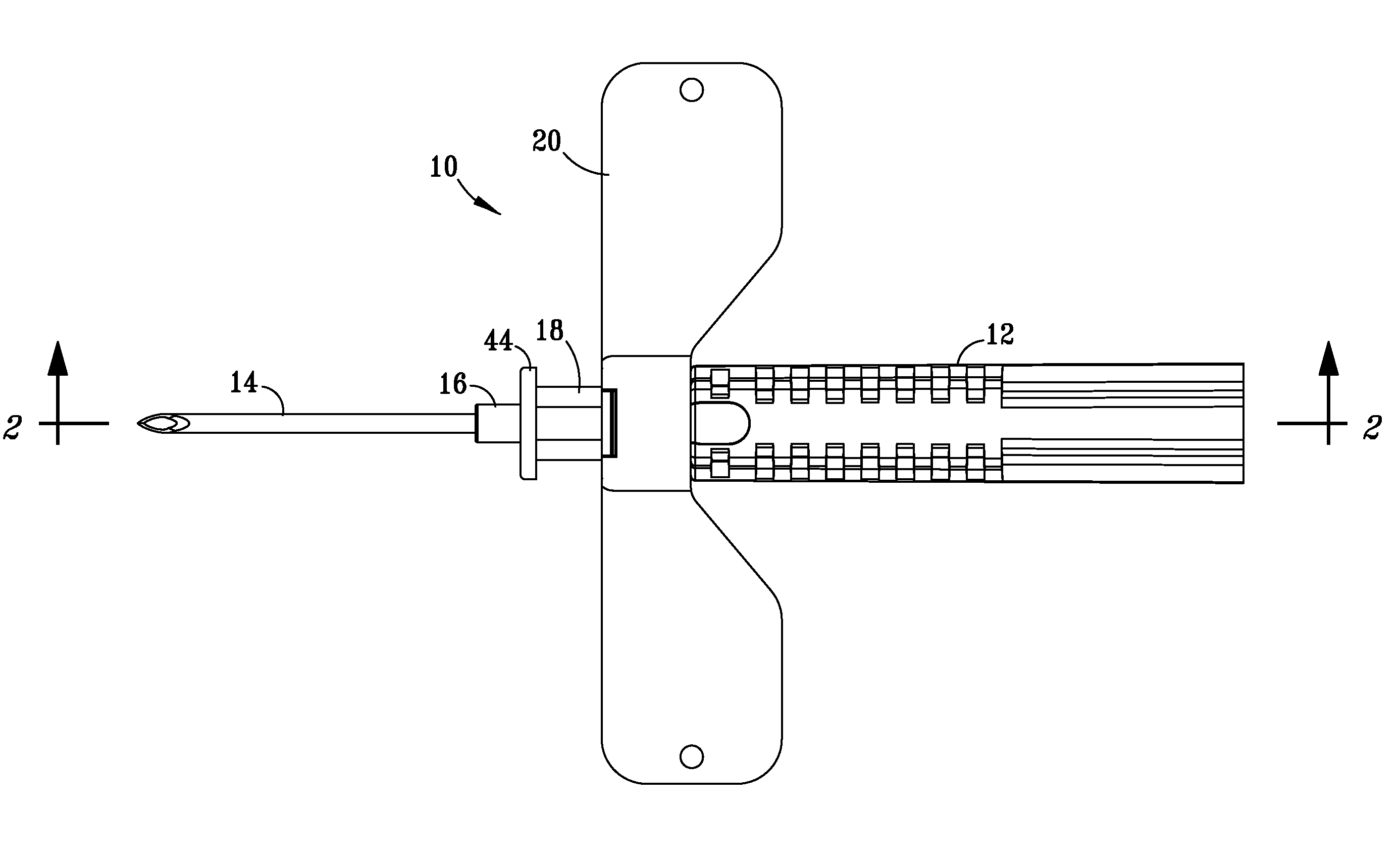
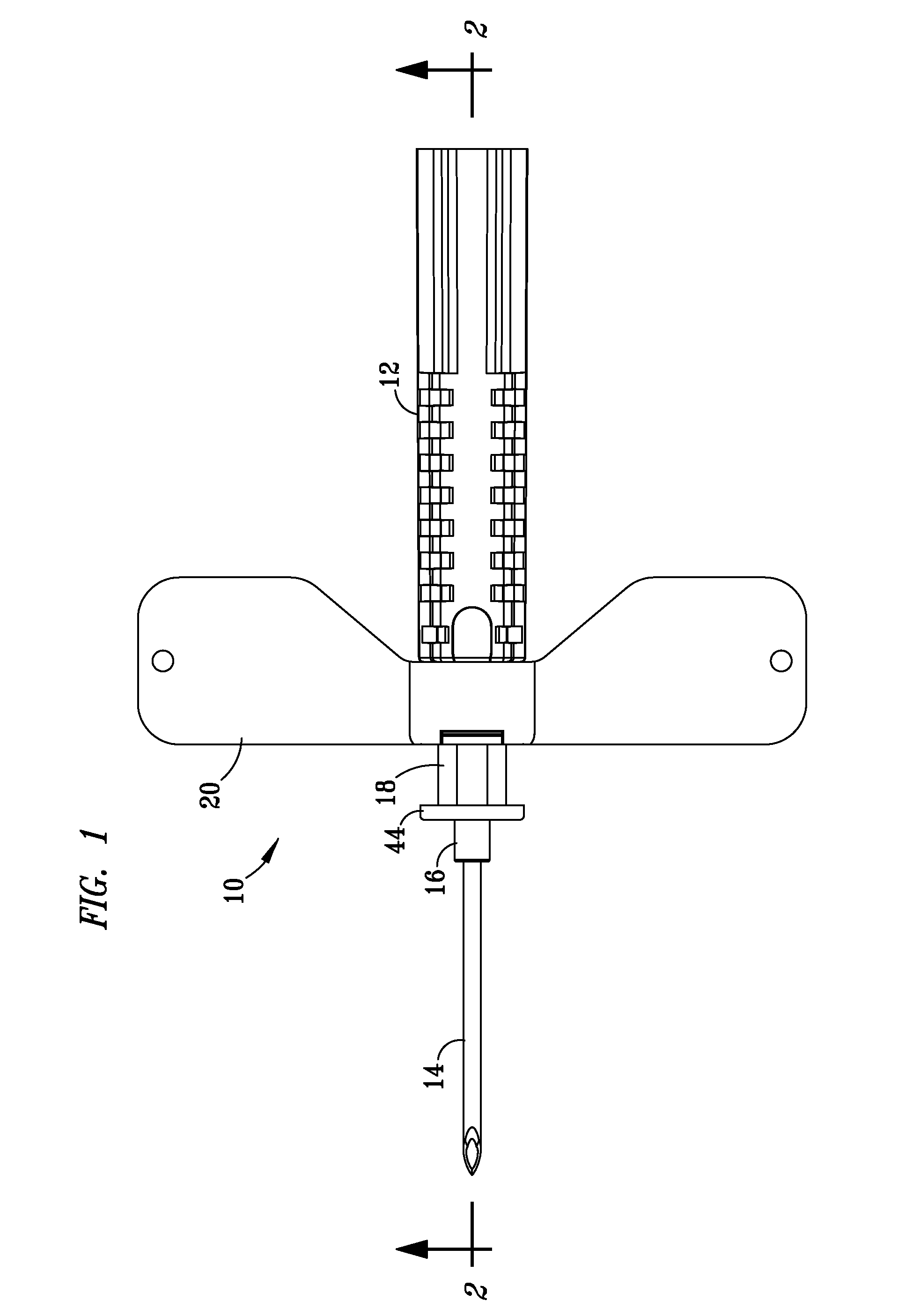
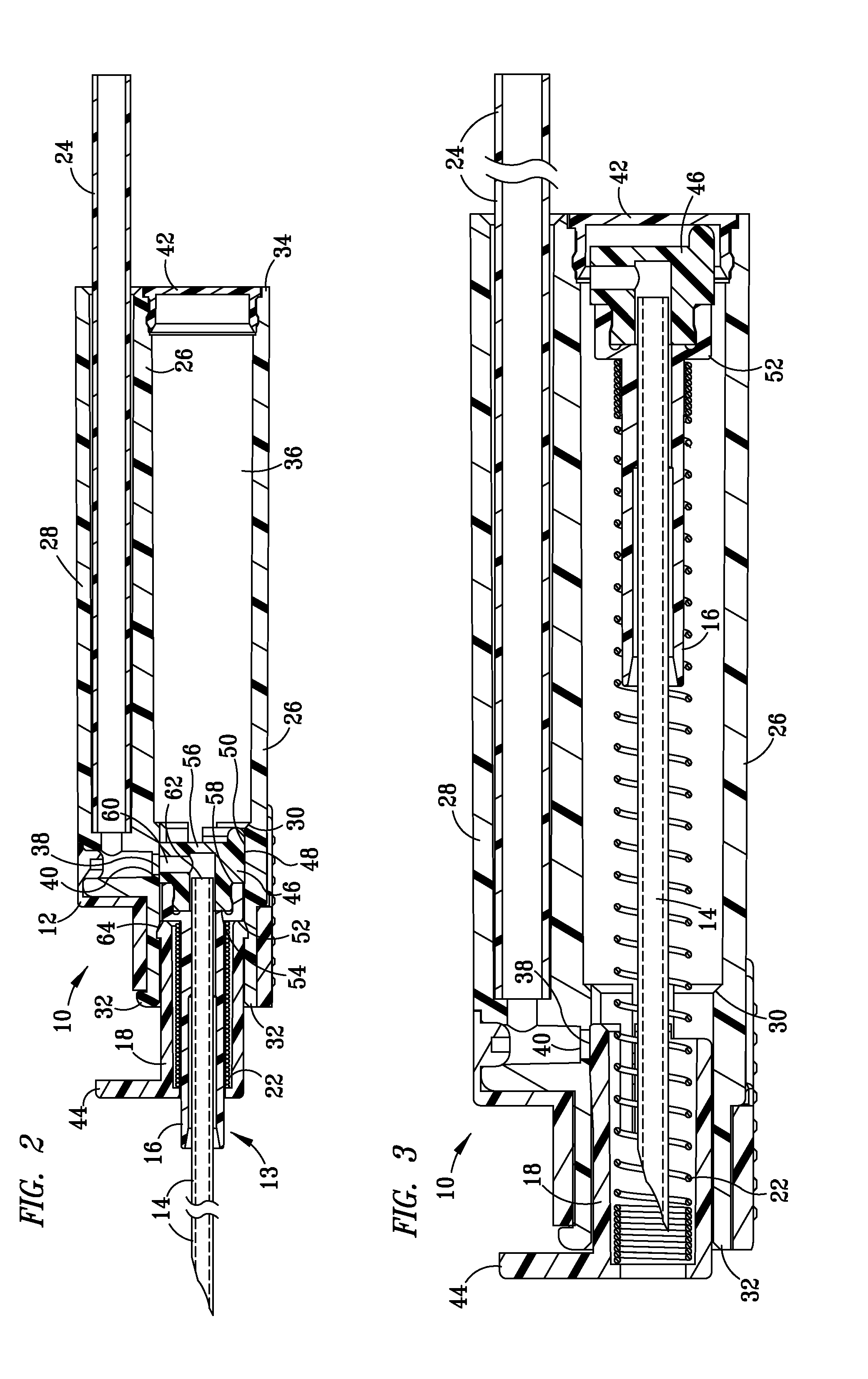
[0034]Referring to FIG. 1, device 10 can be used, for example, as part of a medical apparatus for collecting blood, blood gases or other bodily fluids from a patient, or for infusing a patient with fluids of the type typically administered intravenously or otherwise. As shown, device 10 comprises housing 12 and forwardly projecting cannula 14 attached to cannula holder 16, which is more visible in FIGS. 2 and 3. Prior to use of device 10, the beveled point of cannula 14 is desirably shielded by a protective cover. Actuator 18 is slidably supported by housing 12 and comprises a plurality of opposed flexible latches that secure the end opposite handle 44 inside housing 12. Handle 44 at the front of actuator 18 facilitates manual manipulation of actuator 18 relative to housing 12 to terminate fluid flow through device 10 and initiate retraction of cannula 14 inside housing 12 as described in greater detail below.

[0035]Optional stabilization wings 20 extend laterally from housing 12 and...


PUM


Abstract

A device having a housing; a cannula projecting forwardly from the housing; a connector useful for attaching the device to a fluid source or receptacle; a fluid flow path establishing fluid communication between the cannula and the connector; a retraction mechanism biasing the cannula away from its projecting position; and an actuator supported by the housing and configured to modify the fluid flow path so as to terminate fluid flow through the device, seal off the fluid flow path, and release the retraction mechanism to retract the cannula into the housing. The subject device is particularly preferred for use in the medical field, for example, as part of an infusion set or as a collection device for blood, or other fluids or flowable matter.

Description

BACKGROUND OF THE INVENTION[0001]1. Field of the Invention[0002]This invention relates to a fluid flow control device and, in a preferred embodiment, to a medical device having a cannula, often a needle, that is insertable into a patient for use in infusing, collecting or extracting fluids. One aspect of the invention relates to a medical device having an actuator that is manipulated to modify a fluid flow path between the cannula and an external fluid source or receptacle following the infusion or extraction. Another aspect of the invention relates to a mechanism that functions as a clamp when attached to a fluid flow line. Another aspect of the invention relates to a mechanism that retracts the cannula inside the device to prevent accidental needlesticks following use and to prevent reuse of the contaminated cannula. Although the subject invention is particularly preferred for use in intravascular (“IV”) applications, it can also be used beneficially, for example, in epidural, int...

Claims


Application Information

Patent Timeline
Patent Type & Authority Applications(United States)
IPC IPC(8): A61M5/32A61M5/168
CPCA61M5/158A61M5/3232A61M25/0631A61M5/50A61M25/0637A61M5/3257A61M5/14A61M5/32
Inventor SHAWSMALL, MARKZHU, NI
Owner RETRACTABLE TECH INC
Why Eureka
Try Eureka