External Bone Fixation System

a bone fixation system and bone technology, applied in the field of external bone fixation assembly, can solve the problems of patent failure to teach multiple orientational components, failure to teach the ability to independently rotate,

Active Publication Date: 2014-09-18
TRILLIANT SURGICAL LLC
View PDF13 Cites 63 Cited by
  • Summary
  • Abstract
  • Description
  • Claims
  • Application Information

AI Technical Summary

Benefits of technology

[0015]The apparatus and method of the present invention generally includes an external bone pin assembly that includes a fracture fusion tube for slidably engaging one or more bracket (which may be a clamp or similar structure). At least one bracket is connected to a collet clamp or similar structure which is rotatable around the circumference of the fracture fusion tube. The collet clamp has seated therein a perforated ball for receiving a bone pin therethrough, the ball being rotatable within the collet clamp for adjusting the angle of engagement for the bone pin and the bone. The perforated ball is composed of aluminum or a similar crushable material. The collet clamp and the bracket have aligned apertures, at least one of which is threaded, and a single screw can be aligned with both apertures, such that tightening a single screw will secure the bracket and collet clamp into a fixed position, and the compressive force of the collet clamp from the tightening screw on the perforated ball crimps the ball into a fixed position. Thus, a single screw can fix all of the components from a given pin subassembly extending from the fusion fracture tube.

Problems solved by technology

This patent, however, fails to teach multiple orientational components, such as a slideable bracket, a collet and / or other components which may be fixed in location through the use of a single fastener.
However, Hollawell fails to teach the ability to independently rotate and setting a pin within a collet clamp having a fixed location, nor does it teach the ability to have multiple independently rotatable axes for fixing a pin location wherein the system may be fixed in location using a single fastener.

Method used


Image

  • External Bone Fixation System
  • External Bone Fixation System
  • External Bone Fixation System

Examples


Embodiment Construction

[0027]Set forth below is a description of what is currently believed to be the preferred embodiment or best examples of the invention claimed. Future and present alternatives and modifications to this preferred embodiment are contemplated. Any alternatives or modifications which make insubstantial changes in function, in purpose, in structure or in result are intended to be covered by the claims in this patent.

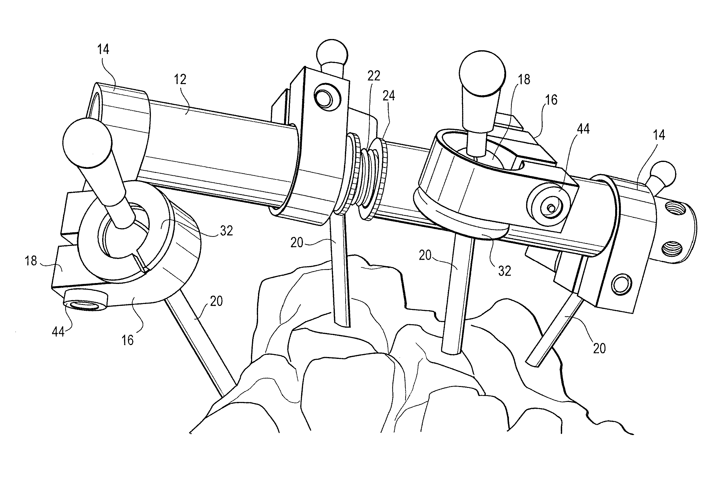
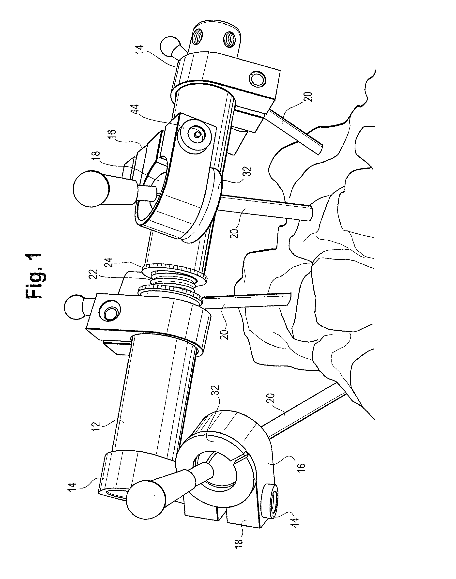
[0028]As can be seen in FIG. 1, in one embodiment of the present invention the assembly 10 comprises a bone fusion tube or rail 12, at least one bracket 14, at least one collet clamp 16 which has seated therein a ball collet 18, the collet clamp 16 being attached to the bracket, and a pin 20 inserted through the ball collet. Generally, the clamp system 10 is configured to connect the rail 12 to the pin 20, which is connected to a bone for fixation and stabilization.

[0029]The rails 12 may be any size or shape, and persons of skill in the art will recognize that different applic...


PUM


Abstract

An external fixation assembly for bone fusion or separation is disclosed. The assembly includes a fracture fusion tube, with a bracket slidably engaged thereon. The assembly further includes a collet clamp connected to the bracket, with a ball collet rotatably seated within the clamp, the ball collet having an aperture for receiving a bone bin therethrough and perforations for a compression engagement with a bone pin. The assembly uses a single screw for threadably engaging the ball collet, the clamp and the bracket such that the position of the bone pin, ball collet and bracket are all fixed.

Description

FIELD OF INVENTION[0001]The present invention relates to an external fixation assembly for bone fusion or separation. More specifically, the assembly includes a fracture fusion tube, with a bracket slidably engaged thereon. The assembly further includes a collet clamp connected to the bracket, with a perforated ball rotatably seated within the clamp, the ball having an aperture for receiving a bone bin therethrough. The assembly uses a single screw for threadably engaging the pin collet, the clamp and the bracket such that the position of the ball, bracket, and collet clamp is fixed. Thus, the present invention teaches an assembly for external fixation with multiple axes of rotation for pin placement and setting wherein the desired placement may be fixed through the use of a single screw or similar connector.BACKGROUND OF THE INVENTION[0002]External fixation devices have been commonly used for various treatments of bone conditions. Such bone conditions include leg lengthening, osteo...

Claims


Application Information

Patent Timeline
Patent Type & Authority Applications(United States)
IPC IPC(8): A61B17/64
CPCA61B17/6416A61B17/6433A61B17/6466A61B17/60
Inventor RICCIONE, NICHOLAS
Owner TRILLIANT SURGICAL LLC
Why Eureka
Try Eureka