Calibrating method for randomly placing fringe projection three-dimensional measuring system

A technology of three-dimensional measurement and fringe projection, applied in the direction of measuring devices, optical devices, instruments, etc., can solve the problems of expensive equipment, impracticality, and demanding system structure design

Active Publication Date: 2014-10-22
UNIV OF ELECTRONICS SCI & TECH OF CHINA
View PDF9 Cites 21 Cited by
  • Summary
  • Abstract
  • Description
  • Claims
  • Application Information

AI Technical Summary

Problems solved by technology

This method has low requirements on the structure setting of the measurement system, but it can only give the phase-height data relationship, and cannot give the calibration method of the abscissa
[0008] It can be seen from the above literature that the existing calibration technology is either complex and difficult to implement, or

Method used


Image

  • Calibrating method for randomly placing fringe projection three-dimensional measuring system
  • Calibrating method for randomly placing fringe projection three-dimensional measuring system
  • Calibrating method for randomly placing fringe projection three-dimensional measuring system

Examples


Embodiment 1

[0058] A full-coordinate calibration method for any fringe projection three-dimensional measurement system, characterized in that it includes the following steps:

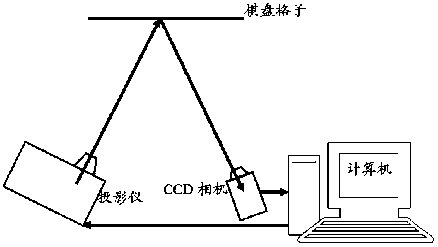
[0059] A. Set up the experimental measurement system: The system mainly includes cameras, projectors, calibration boards, objects to be measured, control computers and brackets. The distribution of projectors, cameras, and calibration boards is arbitrary, and the relative positions are arbitrary. Adjust the system so that the digital camera can capture the stripe patterns on the calibration plate and the surface of the object to be measured.

[0060] B. Place the calibration plate at multiple arbitrary positions in the field of view of the measurement system (in this example, place the calibration plate at 20 different positions arbitrarily). At each position, the computer controls the projector to generate and project 10 standard sinusoidal phase shift fringe patterns, and the digital camera captures the fringe p...

Embodiment 2

[0074] In order to verify the accuracy and validity of the phase-height relationship and the height-abscissa relationship calibrated by the method of the present invention, in the measurement field, the calibration plate is accurately positioned at two positions of 4mm and 16mm relative to the position of the reference surface. Its measurement results are as Figure 8 with Figure 9 shown. The mean values ​​of the measurement results are 4.053mm and 16.057mm respectively, and the corresponding standard deviations are 0.028 and 0.033. For the measurement of the abscissa, we use the spacing of the grid corner points on the calibration board as an evaluation. At 4mm, the mean value in the X direction is 9.968mm, the mean value in the Y direction is 9.977mm, and the corresponding standard deviations are 0.062 and 0.075. At 16mm, the mean value in the X direction is 10.061mm, the mean value in the Y direction is 10.070mm, and the corresponding standard deviations are 0.064 and 0...


PUM


Abstract

The invention provides a calibrating method for randomly placing a fringe projection three-dimensional measuring system. The calibrating method comprises the following steps of: 1, designing a calibrating plate, wherein the calibrating plate is a chessboard pattern with equal intervals; 2, placing the calibrating plate into a measuring system view field for CCD (Charge Coupled Device) camera calibration; 3, placing the chessboard pattern on any different positions in a measurement field, projecting a phase shifting sine fringe pattern to the surface of the chessboard pattern on each placement position, and then collecting images and calculating the distribution phi of an unwrapped phase of each pixel point positioned on the surface of the chessboard pattern and the distance h from the unwrapped phase to a reference surface; 4 establishing three polynomials to express the relationship between the unwrapped phase phi and a height h, between the height h and a horizontal coordinate X and between the height h and a horizontal coordinate Y; 5 converting the horizontal coordinates (X, Y) which are from the unwrapped phase to actual height data and correspond to the height data by utilizing calibrated polynomial coefficient to complete the calibration of the three-dimensional measuring system.

Description

technical field [0001] The present invention relates to a calibration method of an optical three-dimensional measurement system based on fringe projection, specifically measuring the surface phase of an object by using fringe projection technology, establishing the relationship between the unfolded phase and height, and the relationship between height and abscissa, and used for the technology of object three-dimensional surface shape measurement field. Background technique [0002] With the rapid development of precision machining, automobile manufacturing, precision optical processing, semiconductor industry, precision instrument manufacturing, mold design, reverse engineering and other fields, people are increasingly eager to accurately measure precision parts and workpiece objects. Two-dimensional data measurement equipment can no longer meet the increasingly modernized and automated production requirements, and three-dimensional measurement technology has emerged as the ...

Claims


Application Information

Patent Timeline
IPC IPC(8): G01B11/25
Inventor 岳慧敏赵必玉李明阳吴雨祥刘永
Owner UNIV OF ELECTRONICS SCI & TECH OF CHINA
Why Eureka
Try Eureka