
Hybrid generator

a hybrid generator and generator technology, applied in the direction of electric generator control, machine/engine, process and machine control, etc., can solve the problems of failing to recognize opportunities to improve system efficiency, and achieve the effect of achieving the efficient operation speed of the engine and achieving mechanical-to-electric efficiency of 90%

Inactive Publication Date:
View PDF7 Cites 34 Cited by
  • Summary
  • Abstract
  • Description
  • Claims
  • Application Information

AI Technical Summary

Benefits of technology

This patent describes a hybrid generator that can efficiently generate electricity from fuel, and store it in batteries. The generator includes an engine, an alternator, and a controller to maintain the engine's speed. The stored energy can then be converted into usable electricity using a power converter. The method of operation involves startup, cooling, measuring battery power, and generating energy at a selected percentage of the alternator's capacity. This technology allows for efficient generation of electricity and can adjust to changing energy needs.

Problems solved by technology

There exist a number of disadvantages to prior approaches.
Prior approaches have failed to recognize opportunities to improve system efficiency.

Method used


Image

  • Hybrid generator
  • Hybrid generator
  • Hybrid generator

Examples


Embodiment Construction

[0024]Illustrative embodiments are discussed in detail below. While specific embodiments are discussed, it should be understood that this is done for illustration purposes only. In describing and illustrating the embodiments, specific terminology is employed for the sake of clarity. However, the embodiments are not intended to be limited to the specific terminology so selected. A person skilled in the relevant art will recognize that other components and configurations may be used without departing from the spirit and scope of the embodiments. It is to be understood that each specific element includes all technical equivalents that operate in a similar manner to accomplish a similar purpose. The examples and embodiments described herein are non-limiting examples.

[0025]Furthermore, the embodiments detailed below may be combined into a new embodiment and / or various features of the embodiments described below may be combined to form a new embodiment.

[0026]All publications cited herein ...


PUM


Abstract

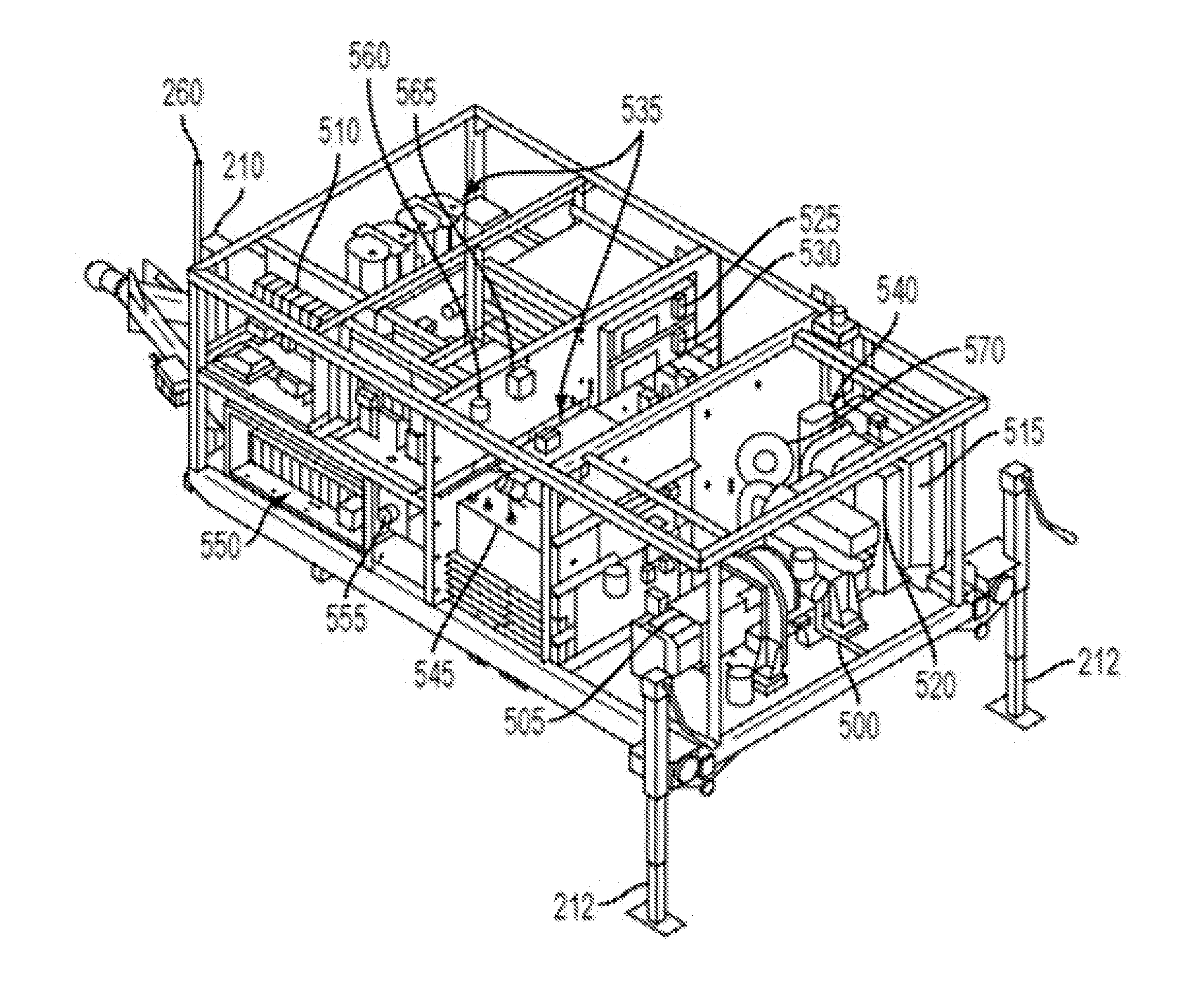
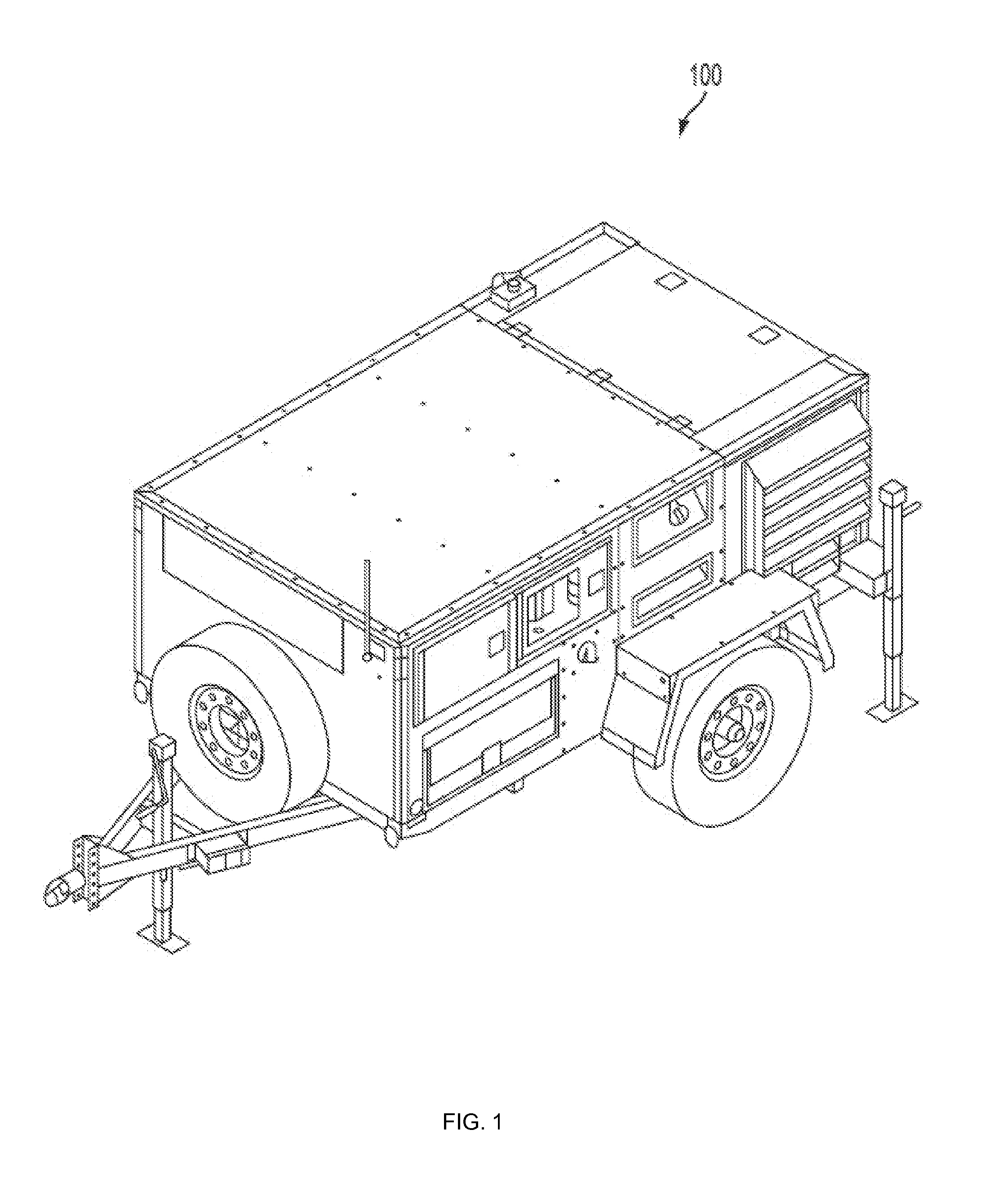
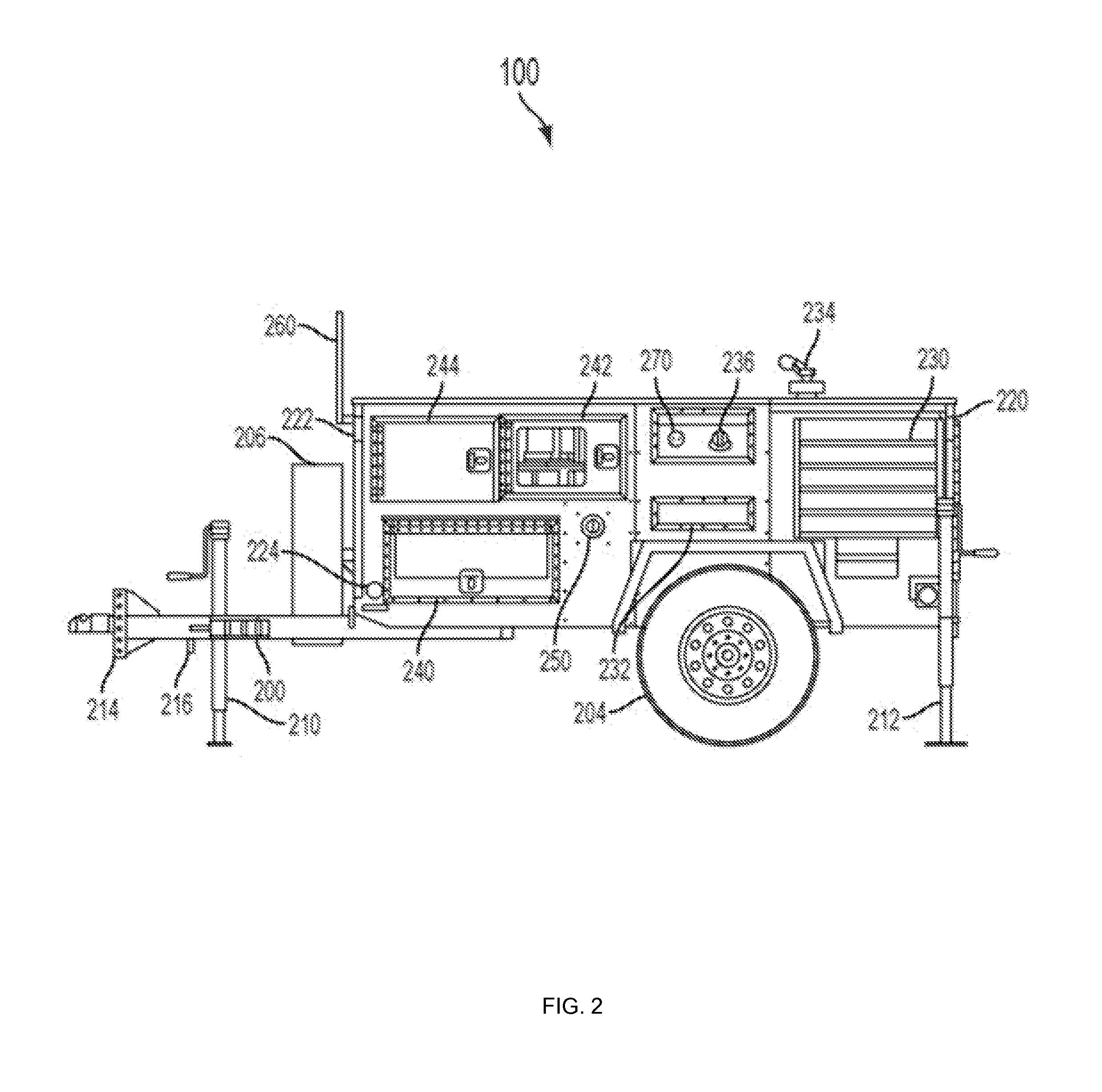
A hybrid generator may include a fuel powered engine; an alternator comprising a permanent magnet alternator head with at least 90% mechanical-to-electric efficiency, the alternator being coupled to the engine; one or more batteries to receive and store power routed from the alternator; a controller to maintain efficient operating speed of the engine at prime power; and a power converter or inverter to convert stored energy from the batteries into usable electricity for AC or DC loads.

Description

CROSS-REFERENCE TO RELATED APPLICATION[0001]This application claims the priority of U.S. Provisional Application No. 61 / 801,468, filed on Mar. 15, 2013, which is incorporated herein by reference in its entirety.FIELD OF INVENTION[0002]The present invention relates to efficient energy production, storage, and manipulation.BACKGROUND OF THE INVENTION[0003]There is a need for improved power for remote sites or where fuel is expensive, locations where a variety of user power needs are required, and also for locations where periods of quiet operations are necessary for operational needs, e.g., hospitals, military sentries, outdoor events, etc.[0004]There exist a number of disadvantages to prior approaches. For example, it is essential to tackle generator system inefficiencies from the time the fuel enters the engine until the power is consumed by the user. Prior approaches have failed to recognize opportunities to improve system efficiency.SUMMARY[0005]Aspects of the invention may involv...

Claims


Application Information

Patent Timeline
Patent Type & Authority Applications(United States)
IPC IPC(8): H02J7/34G05B15/02
CPCG05B15/02H02J7/34F01P3/00F02G5/00H02J7/1438F02D29/06F02B63/04F02G2260/00B60K6/20
Inventor LENARD, ROGER X.MELBERG, ERIC
Learn More