Unlock instant, AI-driven research and patent intelligence for your innovation.

Systems and methods for memory system management based on thermal information of a memory system

a memory system and memory system technology, applied in memory adressing/allocation/relocation, program control, instruments, etc., can solve problems such as data migration becoming more difficult, requiring more refresh cycles, and current die-stacked memory systems with a command interface not currently supporting advanced request priority features

Active Publication Date: 2014-09-18
MICRON TECH INC
View PDF10 Cites 94 Cited by
  • Summary
  • Abstract
  • Description
  • Claims
  • Application Information

AI Technical Summary

Benefits of technology

The patent text describes a system and method for managing thermal issues in memory systems. The system includes a processor and a memory controller connected through a memory system. The memory controller manages memory transactions and transfers data between the processor and the memory system. The system includes a memory system with one or more physical devices mapped to regions based on temperatures stored in a map RAM. The system also includes an operating system and applications running on the processor, with the memory controller mapping applications to physical locations in the memory system. The technical effects of the patent text include reducing hotspots in memory systems, managing energy and resource sharing, and optimizing memory allocation for performance and power requirements.

Problems solved by technology

As temperature increases the DRAM may require more refresh cycles because the retention deteriorates with heat.
While the second memory mapping scheme may have performance benefits, data migration may become more difficult so the necessity data migration will preferably be minimized in example embodiments.
Current die-stacked memory systems with a command interface do not currently support advanced request priority features.
However, the interleaving of the lower two regions may make it more costly to migrate data to other regions if either of the two regions become hot.
For example, some processes may require a certain amount of bandwidth or specific energy requirements for process data.

Method used


Image

  • Systems and methods for memory system management based on thermal information of a memory system
  • Systems and methods for memory system management based on thermal information of a memory system
  • Systems and methods for memory system management based on thermal information of a memory system

Examples


Embodiment Construction

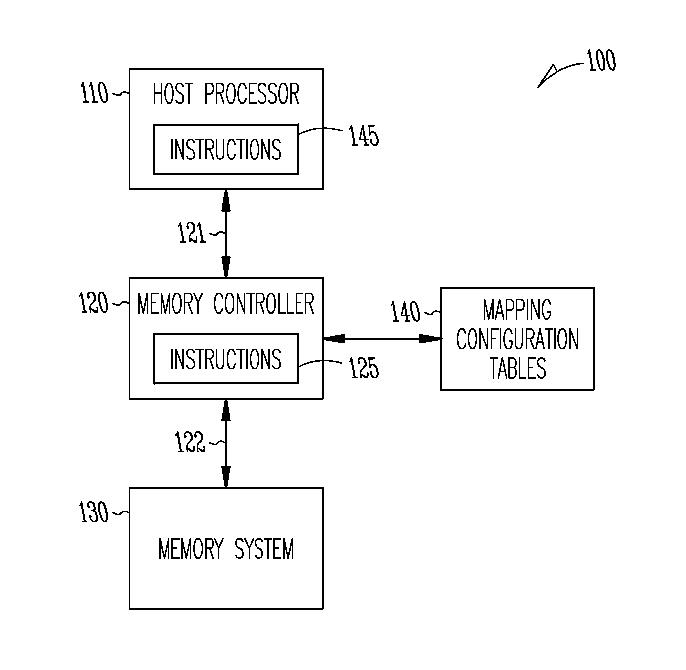
[0016]FIG. 1 is a diagram illustrating a system 100 in which example embodiments may be implemented. The system 100 may include a processor 110 coupled to a memory controller 120 through a first bus 121. The memory controller 120 may be coupled to a memory system 125 through a second bus 122. The memory controller 120 may execute memory transaction requests from the processor 110. The memory controller 120 may transfer data between the processor 110 and the memory system 125 over the first and second buses 121 and 122. The first bus 121 and the second bus 122 may employ a known protocol to connect the processor 110 to the memory controller 120 and to connect the memory controller 120 to the memory system 130. Some examples of system 100 may include personal computers, laptop computers, personal digital assistants (PDAs), digital cameras, electronic games, digital media player / records, and the like.

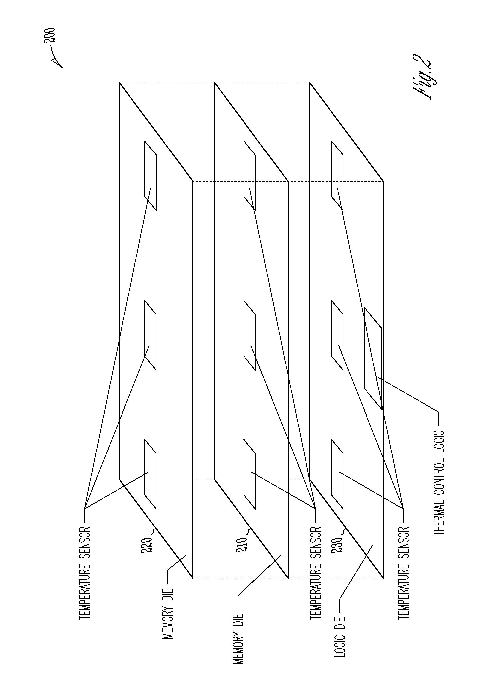
[0017]The memory system 130 may comprise one or more physical devices (not shown) each...


PUM


Abstract

Methods of mapping memory regions to processes based on thermal data of memory regions are described. In some embodiments, a memory controller may receive a memory allocation request. The memory allocation request may include a logical memory address. The method may further include mapping the logical memory address to an address in a memory region of the memory system based on thermal data for memory regions of the memory system. Additional methods and systems are also described.

Description

PRIORITY APPLICATION[0001]This application claims the benefit of priority to U.S. Provisional Application No. 61 / 791,673, filed Mar. 15, 2013, which is incorporated herein by reference in its entirety.BACKGROUND[0002]Memory systems are used in many electronic devices such as personal digital assistants (PDAs), laptop computers, mobile phones and digital cameras. Recent memory chip designs, particularly those that use 3D-stacked structures, may exhibit increased data density and power density. With the use of multi-channel and sub-ranked memories, as well as partitioning of workloads across channels, it is possible for thermal hotspots to arise in the memory system.[0003]Therefore, there exists a general need to perform thermal management, such as by energy management and resource sharing or workload fairness schemes to reduce or eliminate hotspots. There also exists a general need for request stream prioritization and transaction throttling mechanisms for energy management and resou...

Claims


Application Information

Patent Timeline
IPC IPC(8): G06F3/06
CPCG06F3/0631G06F3/068G06F3/0608G06F1/206G06F1/3275G06F12/10G06F13/1668G11C7/04G11C11/40626Y02D10/00G06F3/0604G06F3/0673G06F9/5094G06F12/0223G06F12/023G06F12/122G06F13/24G06F13/4282G06F2212/1016
Inventor WALKER, ROBERTROBERTS, DAVID A.
Owner MICRON TECH INC