
Image processing device, projector, and image processing method

Active Publication Date: 2014-09-25
SEIKO EPSON CORP
View PDF9 Cites 6 Cited by
  • Summary
  • Abstract
  • Description
  • Claims
  • Application Information

AI Technical Summary

Benefits of technology

The invention provides an image processing device, projector, and method that make it easier for users to operate projections.

Problems solved by technology

However, in the interactive system according to related art, since the direction of the projection image projected by the projector is fixed to a predetermined direction, there has been a disadvantage that the projection image is difficult to be viewed by the user depending on the position where the operation is performed.
As described above, there is a problem that the convenience of the user is insufficient when operating the projection image.

Method used


Image

  • Image processing device, projector, and image processing method
  • Image processing device, projector, and image processing method
  • Image processing device, projector, and image processing method

Examples


first embodiment

[0035]Hereinafter, a first embodiment of the invention will be explained in detail with reference to the accompanying drawings.

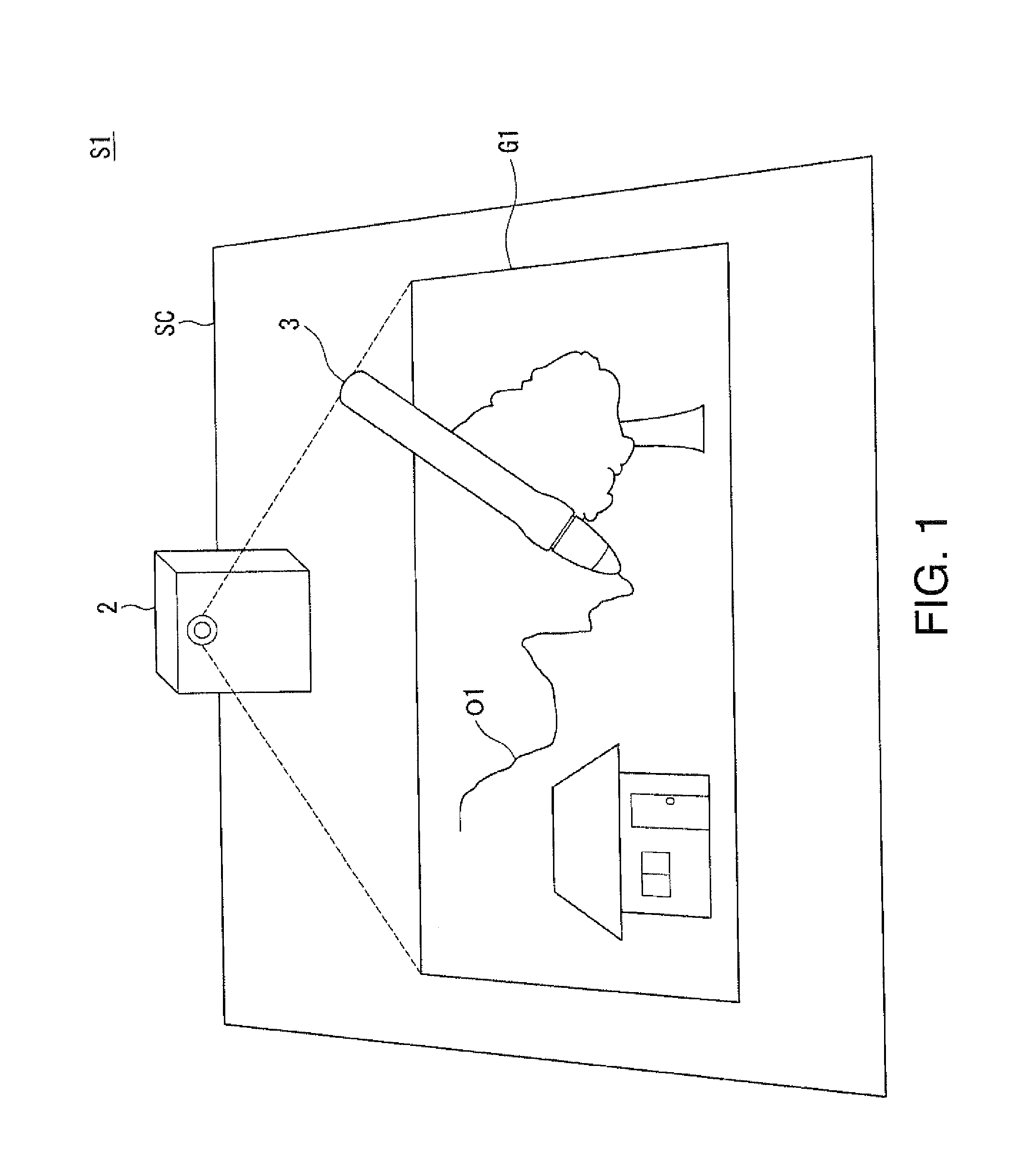
[0036]FIG. 1 is a schematic diagram showing an example of a configuration of an interactive system S1 according to the first embodiment of the invention.

[0037]The interactive system S1 is configured including a projector 2 provided with an image processing device 1, and a light emitting pen 3 as a pointing body.

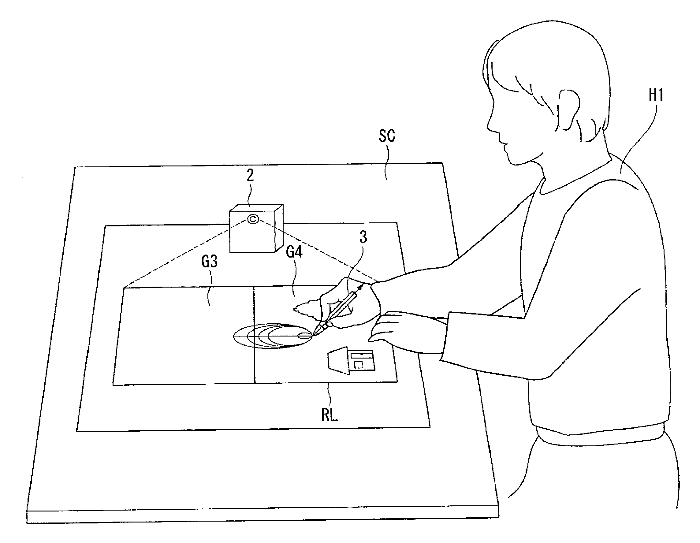
[0038]The projector 2 projects an image G1 on a projection surface SC. The user is allowed to point a part of the image G1 (hereinafter referred to as a projection image) projected, and draw an object O1 such as a figure or a character on the image G1 using the light emitting pen 3. On this occasion, the light emitting pen 3 makes a light emitting element provided to the tip of the light emitting pen 3 emit light to thereby irradiate the projector 2 with an infrared ray, and the projector 2 detects the light emitted by the light emitting pen 3 to reco...

second embodiment

[0068]Hereinafter, a second embodiment of the invention will be explained in detail with reference to the accompanying drawings.

[0069]FIG. 5 is a schematic block diagram showing an example of a configuration of a projector 2A provided with an image processing device 1A according to the second embodiment of the invention.

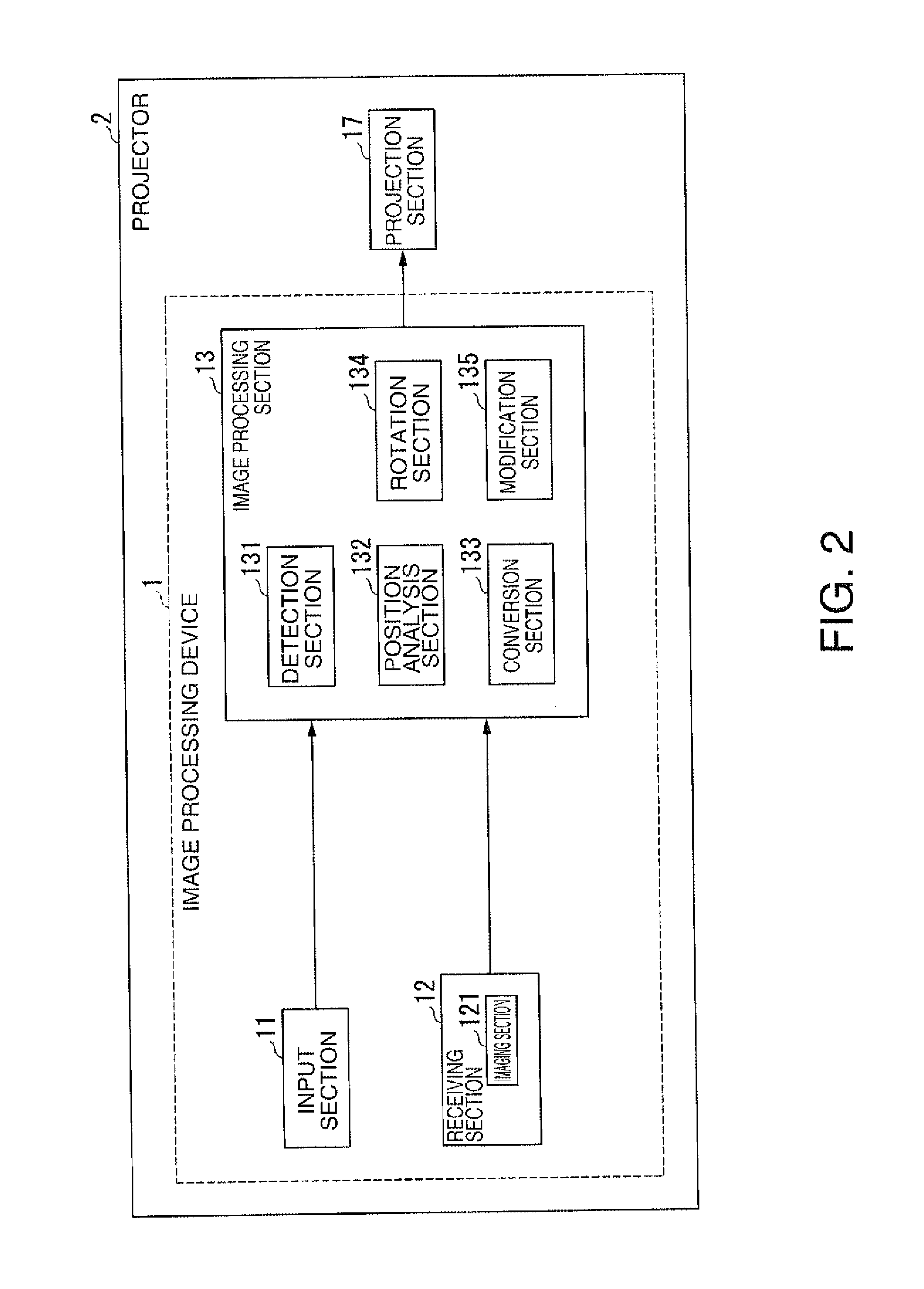
[0070]The projector 2A is configured including the image processing device 1A and the projection section 17. The image processing device 1A is configured including the input section 11, the receiving section 12, the image processing section 13, a control section 14, and a device output section 15. The receiving section 12 is configured including an imaging section 121. The image processing section 13 is configured including a detection section 131A, the position analysis section 132, the conversion section 133, and a rotation section 134A. The detection section 131A is configured including a tilt detection section 1311. Although the projector 2A is provided with func...


PUM


Abstract

An image processing device includes a detection section adapted to detect a pointing direction of a pointing body, and a rotation section adapted to rotate an image based on the pointing direction detected by the detection section.

Description

[0001]The entire disclosure of Japanese Patent Application No 0.2013-061568, filed Mar. 25, 2013 is expressly incorporated by reference herein.BACKGROUND[0002]1. Technical Field[0003]The present invention relates to an image processing device, a projector, and an image processing method.[0004]2. Related Art[0005]There has been known an interactive system provided with a projector for projecting an image, and a light emitting pen operated by the user on the image projected (see, e.g., JP-A-2012-173447). The light emitting pen is a pointing body for emitting an infrared ray from the pen tip, and the projector detects the infrared ray from the light emitting pen to recognize the operation content of the user.[0006]When the projector projects a projection image on a horizontal projection surface such as a desk, the user performs the operation in a variety of positions in the periphery of the desk in some cases. However, in the interactive system according to related art, since the direc...

Claims


Application Information

Patent Timeline
IPC IPC(8): G06T3/60G06F3/0354
CPCG06F3/03542G06T3/60G06F3/0425
Inventor KOYAMA, TAKAAKI
Owner SEIKO EPSON CORP
Learn More