
Stereoscopic display device

a stereoscopic display and display device technology, applied in the field of stereoscopic display devices, can solve the problems of viewer discomfort or tiredness, inability to perceive a proper stereoscopic image, etc., and achieve the effect of responding sufficiently quickly

Active Publication Date: 2014-09-25
SHARP KK
View PDF10 Cites 10 Cited by
  • Summary
  • Abstract
  • Description
  • Claims
  • Application Information

AI Technical Summary

Benefits of technology

The present invention provides a display that can be viewed from different angles and allows for stereoscopy.

Problems solved by technology

Consequently, if the viewer is not at the optimum viewing position, he does not perceive a proper stereoscopic image.
These phenomena may cause the viewer to feel uncomfortable or tired.

Method used


Image

  • Stereoscopic display device
  • Stereoscopic display device
  • Stereoscopic display device

Examples


embodiment

[0037]Now, embodiments of the present invention will be described in detail with reference to the drawings. The same or corresponding components in the drawings are labeled with the same characters and their description will not be repeated. For ease of understanding, the drawings to which reference will be made hereinafter show simplified or schematic representation, or do not show some components. The size ratios of the components shown in the drawings do not necessarily represent the actual size ratios.

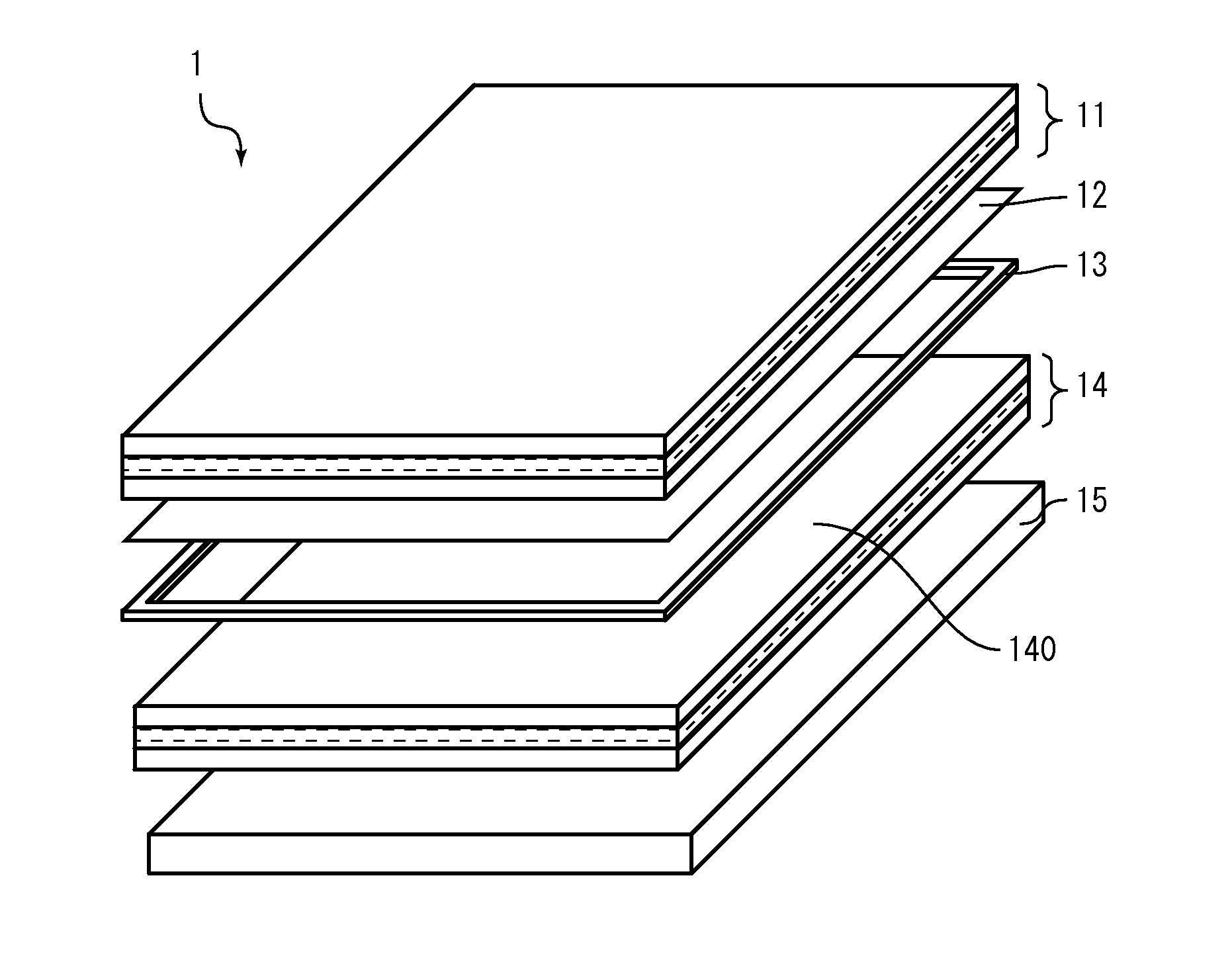
[0038]FIG. 1 is an exploded schematic perspective view of a stereoscopic display device 1 according to an embodiment of the present invention. The stereoscopic display device 1 includes a liquid crystal lens 11, a retarder 12, a spacer 13, a liquid crystal display 14, and a backlight 15.

[0039]Each of the liquid crystal lens 11 and liquid crystal display 14 is in the shape of a plate that is generally rectangular in a plan view, and includes main faces (i.e. the set of opposite face...

first embodiment

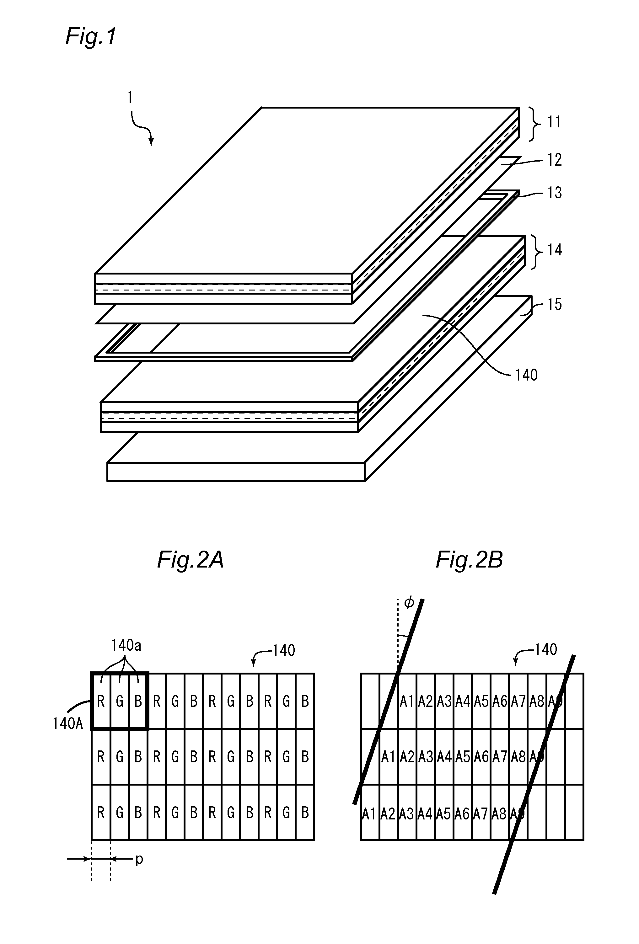
[0096]A stereoscopic display device 1 is designed where the inter-viewpoint distance E=16.25 mm, the number of viewpoints N=9, and the liquid crystal display 14 is a full high-definition (resolution: 1920×1080 pixels) display with a diagonal size of 42 inches (1066.8 mm). The liquid crystal display 14 has square pixels 140A, each divided equally into red, green and blue subpixels 140a arranged in a horizontal direction. Then, a pixel 140A has a side of about 484.5 μm, and the interval p of the subpixels 140a as measured in a horizontal direction is about 161.5 μm. Angle φ is 18.4°.

[0097]Generally, the optimum distance from which to view the display is three times the vertical size of the display. Now, a design of various elements will be described based on the condition that the optimum viewing distance S2 is 1.6 m.

[0098]Equation (2) gives S1=14.902 mm. Equation (3) gives L=1439.199 um, and Equation (1) gives L1=1365.342 μm. Further, Equation (4) gives f=14.745 mm.

[0099]A case will ...

second embodiment

[0102]In the first embodiment, a case where the viewing distance S2 is longer than its normal value has been discussed. Next, a case where the viewing distance S2 is smaller than its normal value will be discussed.

[0103]When the viewing distance S2 is smaller, reductions in the inter-viewpoint distance E must be taken into consideration. As the inter-viewpoint distance E decreases, the viewing range VR decreases, as well (see FIG. 8). If the viewing range VR is smaller than the distance between the eyes (generally assumed to be 65 mm), a stereoscopic image cannot be viewed. Thus, for 9 viewpoints, for example, the inter-viewpoint distance E must be at least 65 mm / 8=8.125 mm or larger. To give some margin to this value, a stereoscopic display device 1 is designed such that the inter-viewpoint distance E for viewing at the smallest viewing distance S2 is 16.25 mm.

[0104]For example, if a stereoscopic display device 1 is designed that can be viewed properly when the viewing distance S2=...


PUM


Abstract

A stereoscopic display device is provided that enables stereoscopy for various viewing positions. A stereoscopic display device (1) includes: a display panel (14) configured to display images for a plurality of viewpoints, the images having parallax and being arranged regularly; a light beam convertor (11) disposed adjacent the front side of the display panel (14) configured to form virtual lenticular lenses by controlling a voltage, the lenticular lenses adapted to the images on the display panel (14) and being arranged at a certain interval; and a controller configured to control the display panel (14) and the light beam convertor (11). The controller changes the focal length of the virtual lenticular lenses formed by the light beam convertor (11) depending on the distance between the display panel (14) and a viewer.

Description

TECHNICAL FIELD[0001]The present invention relates to a stereoscopic display device, and more particularly, a stereoscopic display device that enables naked eye stereoscopy.BACKGROUND ART[0002]Stereoscopic display devices that do not require special glasses or the like to be worn, or that enable so-called naked eye stereoscopy, are known. JP 2007-336002 A discloses a so-called multi-view stereoscopic display device.[0003]The stereoscopic display device of JP 2007-336002 A generally operates on the following principle: the stereoscopic display device displays images captured in multiple directions, where the images are arranged regularly on the display surface. In front of the display surface, a plurality of lenticular lenses are arranged at a certain interval. The lenticular lenses separate the images captured in multiple directions. The user views the display device at the optimum position to view the separated images with his left and right eyes, and thus experiences stereoscopy c...

Claims


Application Information

Patent Timeline
IPC IPC(8): H04N13/04G09G3/36G02B30/28
CPCH04N13/0447H04N13/0404H04N13/0468G09G3/3648G09G2320/068G09G2300/08G09G2354/00G09G2320/028G09G3/3607G03B35/24G02F1/134309G02F1/13471G02F2201/18G02F2203/18G02F2203/28G02F2203/62H04N13/144H04N13/305H04N13/351H04N13/366H04N13/398G02F1/294G02B30/28G02B30/27
Inventor USUKURA, NARU
Owner SHARP KK
Learn More