
Method and device for supporting group handover

a group and handover technology, applied in the field of mobile communications systems, can solve the problems of failure of the handover process, no specific solution about the current mobility of the group, waste of network resources, etc., and achieve the effect of reducing the possibility of network congestion and unnecessary signaling procedures

Active Publication Date: 2014-09-25
SAMSUNG ELECTRONICS CO LTD
View PDF9 Cites 20 Cited by
  • Summary
  • Abstract
  • Description
  • Claims
  • Application Information

AI Technical Summary

Benefits of technology

The present invention provides a solution to support continuous data transmission during high-speed movement, reduce unnecessary signaling procedures and network congestion, and ensure service continuity during handover. This can be applied to different network architectures and cell identifiers, and can reduce the failure of handover and ensure service continuity.

Problems solved by technology

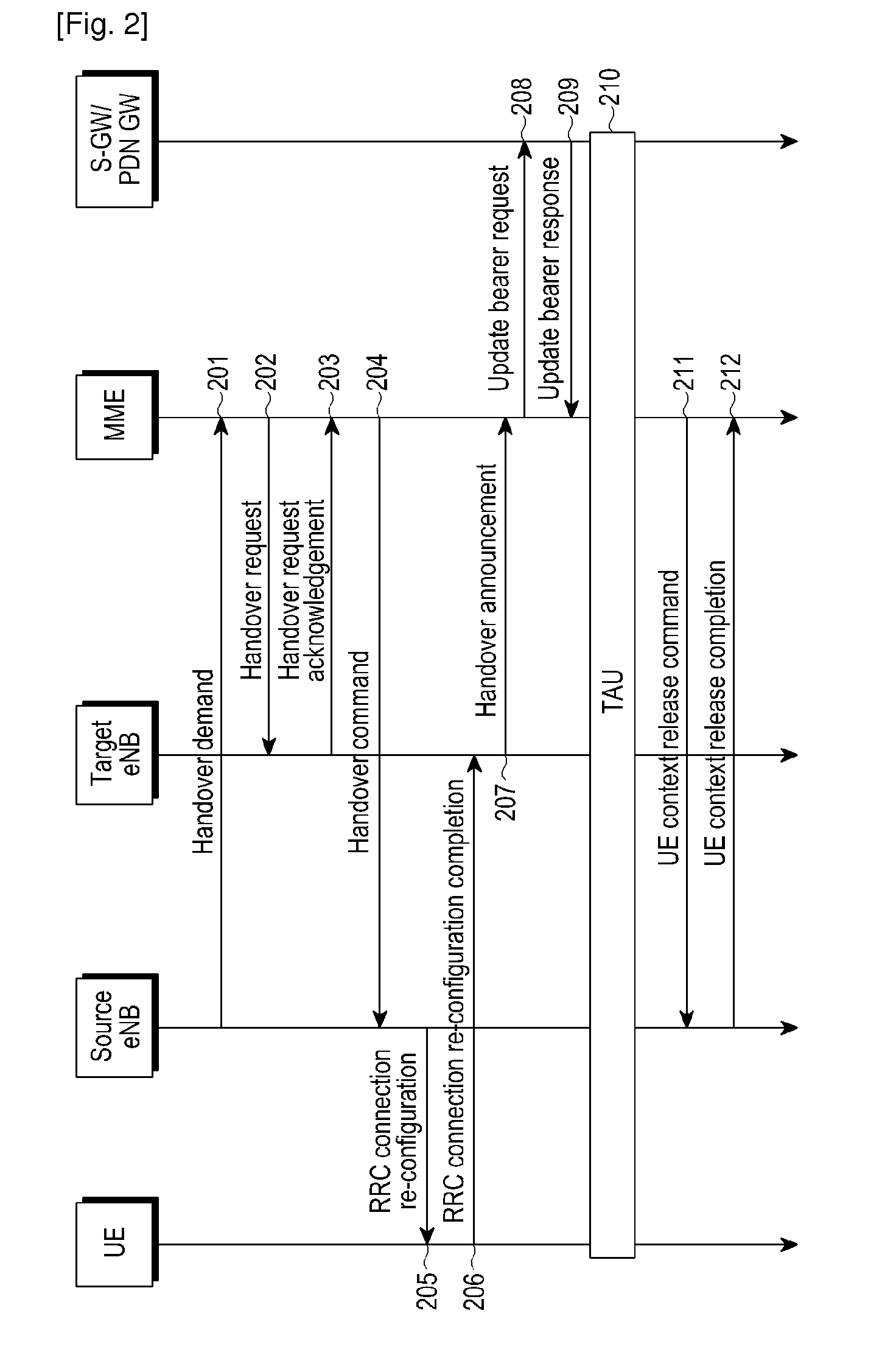
X2 handover process via macro base stations (that is enhanced Node Bs: eNBs) is more optimal than S1 handover via a management Entity (MME) and a Serving Gateway (S-GW) of a core network, whereas Relay Node (RN) and UE both are moving on the train advancing at a high speed, and if multiple UEs simultaneously perform handover process, it will lead to unnecessary resource waste for network and will easily lead to failure of handover process.
In order to solve the problem of low handover success rate and improve the efficiency of handover, the concept of group mobility is set forth, but there is no specific solution about how group mobility does now.
If RN and UEs served by the RN simultaneously perform handover process, how to ensure coordinated work is also a problem that cannot be ignored.
In addition, there are two other problems:
So the problem is how to select MME serving the UE, how to transmit context information of UE, and how to establish user plane transmitting path at network side for UE.

Method used


Image

  • Method and device for supporting group handover
  • Method and device for supporting group handover
  • Method and device for supporting group handover

Examples


Embodiment Construction

[0024]The embodiments of the present invention are specifically described below, and are illustrated in the drawings, wherein the same or similar reference signs always represent same or similar components or components having the same or similar functions. The following embodiments with reference to the accompanying drawings are exemplary and are only used to explain the present invention, but cannot be explained as limiting the present invention.

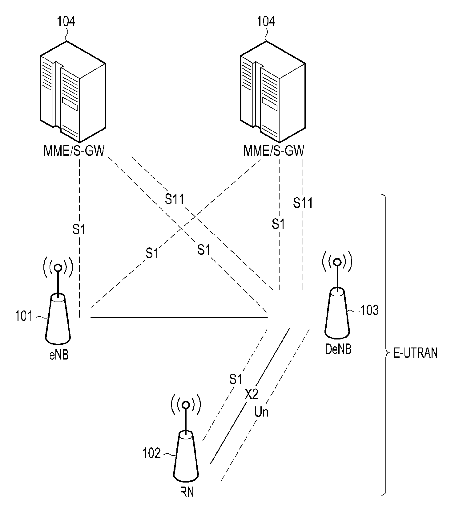
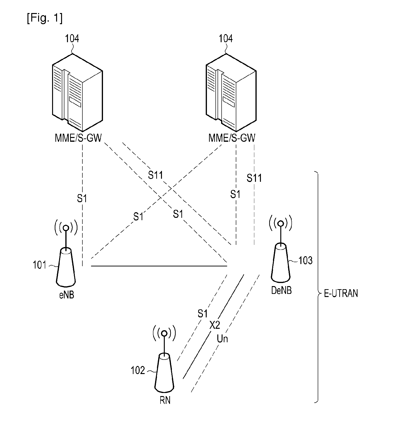
[0025]FIG. 1 is a schematic diagram of the structure of the LTE (Long-Term Evolution) system supporting relay nodes (RN).

[0026]As illustrated in FIG. 1, it is a schematic diagram of the structure of the existing LTE supporting relay nodes (RN). In a wireless access network of the LTE system, a wireless resource management entity includes a macro base station (eNB) 101 and a RN 102, and RN accesses a core network via another macro base station (DeNB) 103. DeNB is a base station for RN access and is called Donor eNB, wherein eNBs 101 are con...


PUM


Abstract

The method and the device for supporting group handover are disclosed. The method supporting group handover is provided, which is applied to UE in communication with network via a RN, including: a base station S-DeNB switching RN to a base station T-DeNB; and said S-DeNB switching UE served by said RN to said T-DeNB; wherein the MME serving said RN and the MME serving UE served by said RN are the same. Another embodiment of the present invention further provides a base station supporting group handover, The technical scheme set forth in the present invention can reduce unnecessary signaling procedure, the possibility of network congestion, and can reduce the signaling procedure of handover when group handover occurs, so as to reduce the failure of the handover process and ensure the continuity of service.

Description

TECHNICAL FIELD[0001]The present invention relates to mobile communications system field and, in particular, to a method and device for supporting group handover.BACKGROUND ART[0002]The existing handover process that each User Equipment (UE) needs interaction of dozens of messages to perform each handover process. X2 handover process via macro base stations (that is enhanced Node Bs: eNBs) is more optimal than S1 handover via a management Entity (MME) and a Serving Gateway (S-GW) of a core network, whereas Relay Node (RN) and UE both are moving on the train advancing at a high speed, and if multiple UEs simultaneously perform handover process, it will lead to unnecessary resource waste for network and will easily lead to failure of handover process. In order to solve the problem of low handover success rate and improve the efficiency of handover, the concept of group mobility is set forth, but there is no specific solution about how group mobility does now.[0003]If RN and UEs served...

Claims


Application Information

Patent Timeline
IPC IPC(8): H04W36/28
CPCH04W8/186H04W36/28H04W92/20H04W36/0055H04W36/0058
Inventor XU, LIXIANGWANG, HONG
Owner SAMSUNG ELECTRONICS CO LTD
Learn More