
Handover method with link failure recovery, wireless device and base station for implementing such method

a technology of link failure recovery and handover method, applied in the direction of network traffic/resource management, transmission system, instruments, etc., can solve the problems of security breach, reduce the probability of wireless device switching to idle, etc., to reduce the probability, reduce security risk, and diversify the effect of authentication data

Active Publication Date: 2009-03-05
VIVO MOBILE COMM CO LTD
View PDF17 Cites 220 Cited by
  • Summary
  • Abstract
  • Description
  • Claims
  • Application Information

AI Technical Summary

Benefits of technology

The patent proposes a handover method for a wireless communication system that ensures secure and efficient communication between a wireless device and a network. The method involves transmitting a first message from a source base station to a target base station servicing a target cell, the first message containing an identifier of the wireless device and information for obtaining authentication data. The wireless device then selects a cell and sends a reestablishment request message to the selected cell, requesting authentication data. The target base station verifies the authentication data and transfers the communication link to the selected cell if the data is conforming. This method reduces the risk of a security breach and ensures smooth communication during handovers.

Problems solved by technology

Due to the possibility of a link failure during execution of the handover procedure, it may be a good idea for the network to prepare more than one target base station in parallel because it reduces the probability of getting the wireless device switched to an idle state and involved in more complex signaling to recover a connection to the network.
If the different target base stations use the same authentication data, a security breach may exist.

Method used


Image

  • Handover method with link failure recovery, wireless device and base station for implementing such method
  • Handover method with link failure recovery, wireless device and base station for implementing such method
  • Handover method with link failure recovery, wireless device and base station for implementing such method

Examples


Embodiment Construction

[0062]A handover process in case of radio link failure is depicted in FIG. 4 in the particular, non-limiting context of an LTE system.

[0063]The beginning of the procedure up to step S6 is quite similar to that of the procedure discussed above with reference to FIG. 3 and will not be described again here. However, step S4 in which the HANDOVER REQUEST message is transmitted from the source eNodeB 20S to a target eNodeB 20T is modified (step S4′) to include in the HANDOVER REQUEST message (or in a separate message sent along with the HANDOVER REQUEST message), in addition to the identifier of the UE 10 for which the handover procedure is initiated, information making it possible to obtain authentication data in the form of an authentication vector. The HANDOVER REQUEST message is received by each target eNodeB 20T by means of its network X2 interface.

[0064]It is important to note that the HANDOVER REQUEST message can be sent to several target eNodeBs selected in step S3, in order to c...


PUM


Abstract

For each target cell determined by a handover decision process, a first message is transmitted from a source base station (20S) to a target base station (20T) servicing that target cell. The first message includes an identifier of a wireless device (10) having a communication link with the source base station and information for obtaining authentication data for this wireless device. The authentication data depends on a secret key available to the wireless device and the source base station and on an identity of the target cell. Upon failure of the communication link, a cell is selected at the wireless device, which transmits to that cell a reestablishment request message including its identifier and authentication data depending on the secret key and on an identity of the selected cell. If the selected cell is a target cell serviced by a target base station that received a first message, conformity of the authentication data included in the reestablishment request message with the authentication data obtained from this first message is verified to authorize transfer of the communication link to the selected cell.

Description

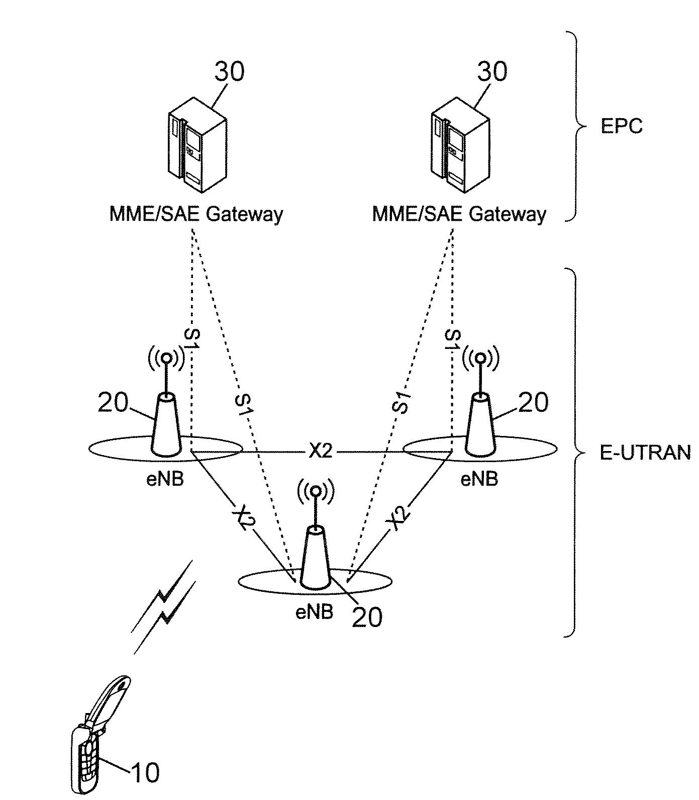
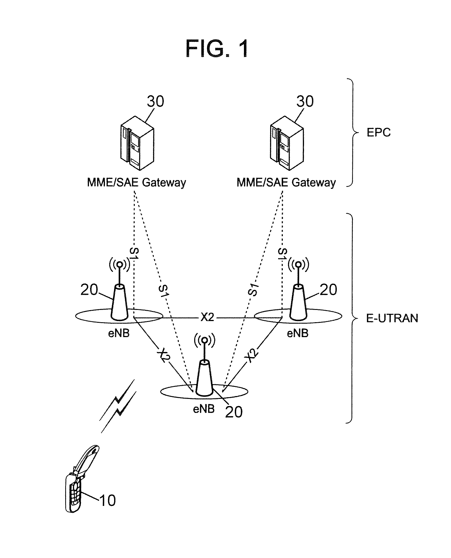
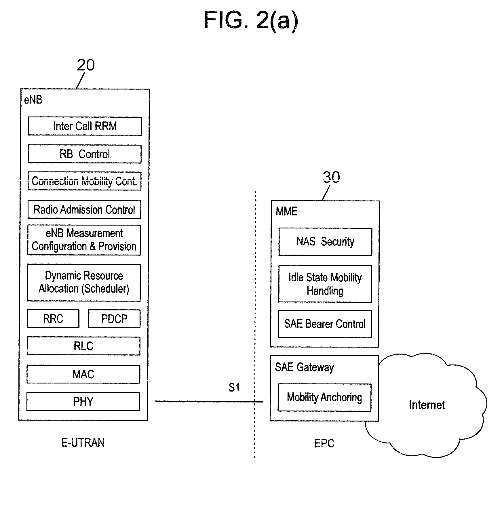
CROSS-REFERENCE TO RELATED APPLICATIONS[0001]This application claims priority of US Provisional Application No. 60 / 955,382 filed on Aug. 12, 2007, the content of which is incorporated herein by reference.BACKGROUND OF THE INVENTION[0002]1. Field of the Invention[0003]The present invention relates to mobility management for wireless devices in a cellular communications network, and in particular to controlling handover of a wireless device from one cell of the network to another. While it is described below in the context of an LTE (“long term evolution”) type of cellular network for illustration purposes and because it happens to be well suited to that context, those skilled in the communication art will recognize that the invention disclosed herein can also be applied to various other types of cellular networks.[0004]2. Discussion of the Related Art[0005]Universal mobile telecommunications system (UMTS) is a 3rd Generation (3G) asynchronous mobile communication system operating in ...

Claims


Application Information

Patent Timeline
Patent Type & Authority Applications(United States)
IPC IPC(8): H04W36/00H04M1/00H04L47/30
CPCG08C17/02H04W88/02H04L47/10H04L47/14H04L47/263H04L47/30H04L47/33H04L47/38H04W28/12H04W72/1252H04W72/1284H04W28/0278H04W28/065H04W72/042H04W28/06G08C2201/32H04L69/04H04W36/0094H04W72/52H04W72/21H04W28/0252H04W8/04H04W72/23H04W88/08
Inventor FISCHER, PATRICK
Owner VIVO MOBILE COMM CO LTD
Learn More