
Device and method for controlling a filling machine

Active Publication Date: 2014-09-25
ALBERT HANDTMANN MASCHFABRICK
View PDF11 Cites 0 Cited by
  • Summary
  • Abstract
  • Description
  • Claims
  • Application Information

AI Technical Summary

Benefits of technology

The patent describes a method and device for controlling a filling machine with a clipping machine. The invention allows for easy adjustment of the functions of the machines, preventing unreliable performance. By exchanging information between the machines, the method ensures that the ejected portion is not decelerated or the filling ejection does not drive against the closed scissors. The filling and clipping machines can be synchronized regardless of changes in speed or volume, especially with high production cycles or small portion sizes. The communication interface allows for a common operator panel for both the clipping and filling machines, facilitating the operator's work. The embodiment with a non-interrupting passage speed is especially useful for small portions.

Problems solved by technology

These problems are strongest with a high portioning cycle and a small portioning volume (ratio of portioning time to portioning pause <3).
There already exists a functioning, but very error-prone and complex / expensive solution for matching the functions of the clipping machine and the filling machine.
While it is possible with the existing parameters to adjust the synchronization between the filling and clipping machines, adjustment is in practice performed step by step and takes a lot of time.
For example, as soon as the speed is adjusted at the filling machine, this time-consuming readjustment must be repeated, which is often not done in practice and may lead in turn to incorrectly adjusted machines.

Method used


Image

  • Device and method for controlling a filling machine
  • Device and method for controlling a filling machine
  • Device and method for controlling a filling machine

Examples


case 1

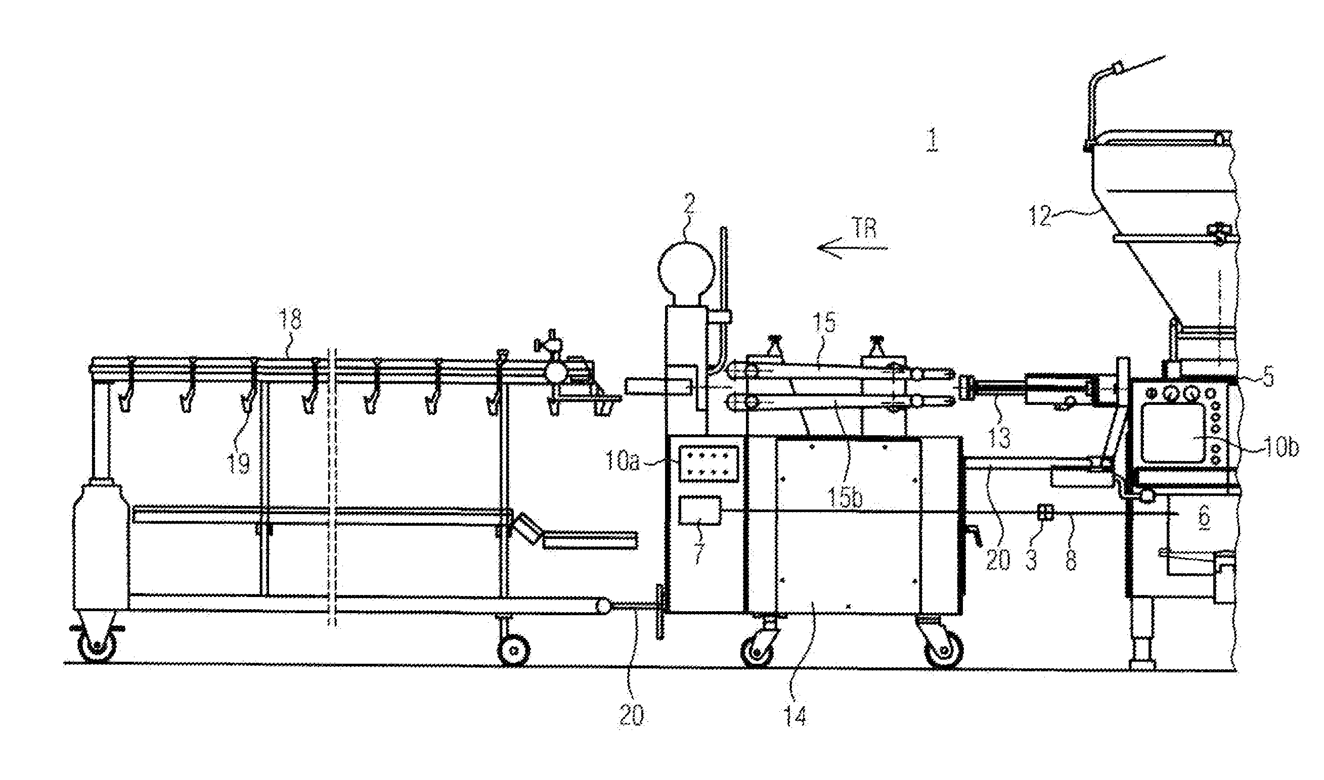
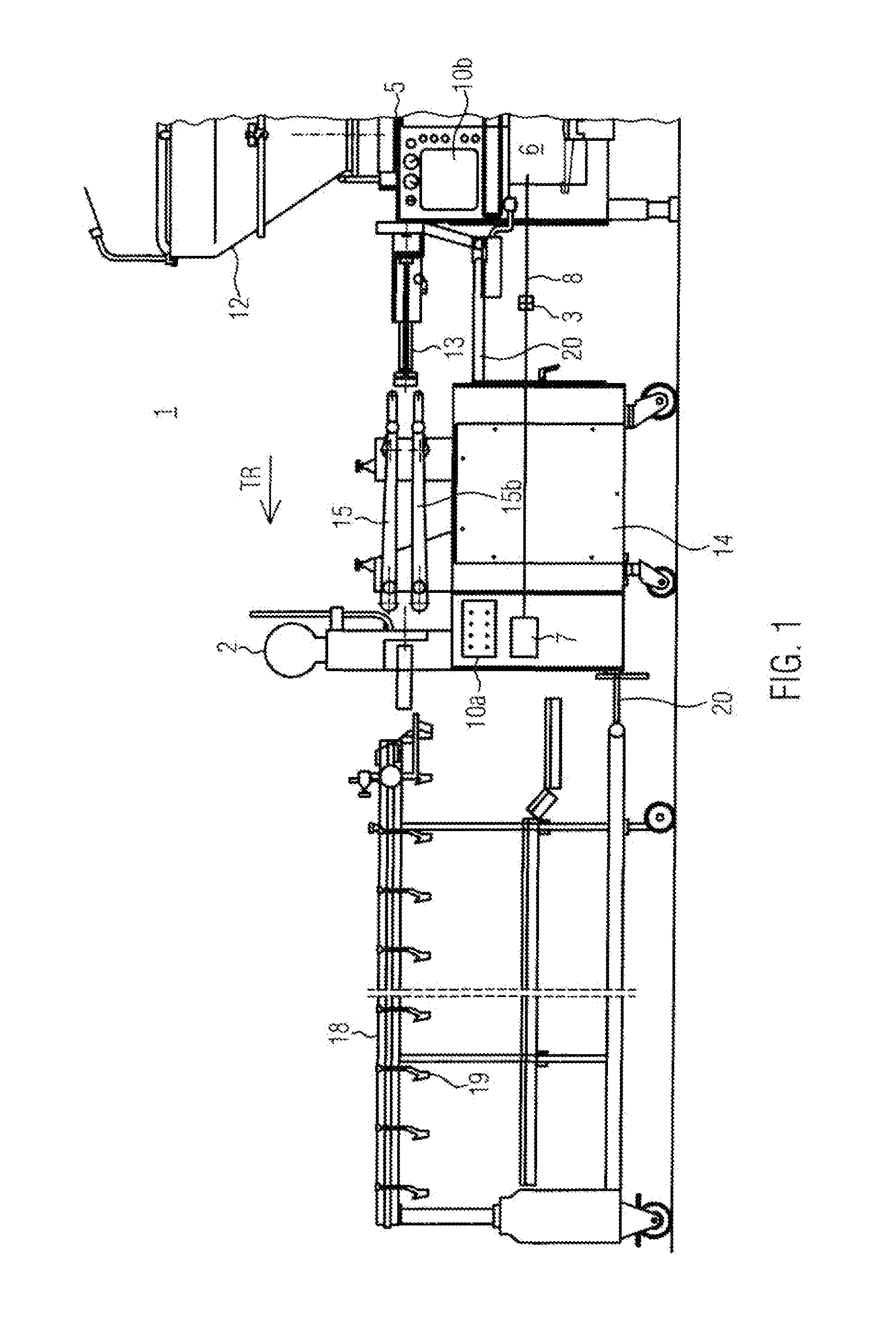
[0079]now described for the case of a relatively large portion of 60 cm3, where with a given clipper acceleration, the clipper scissors are waiting.

case 2

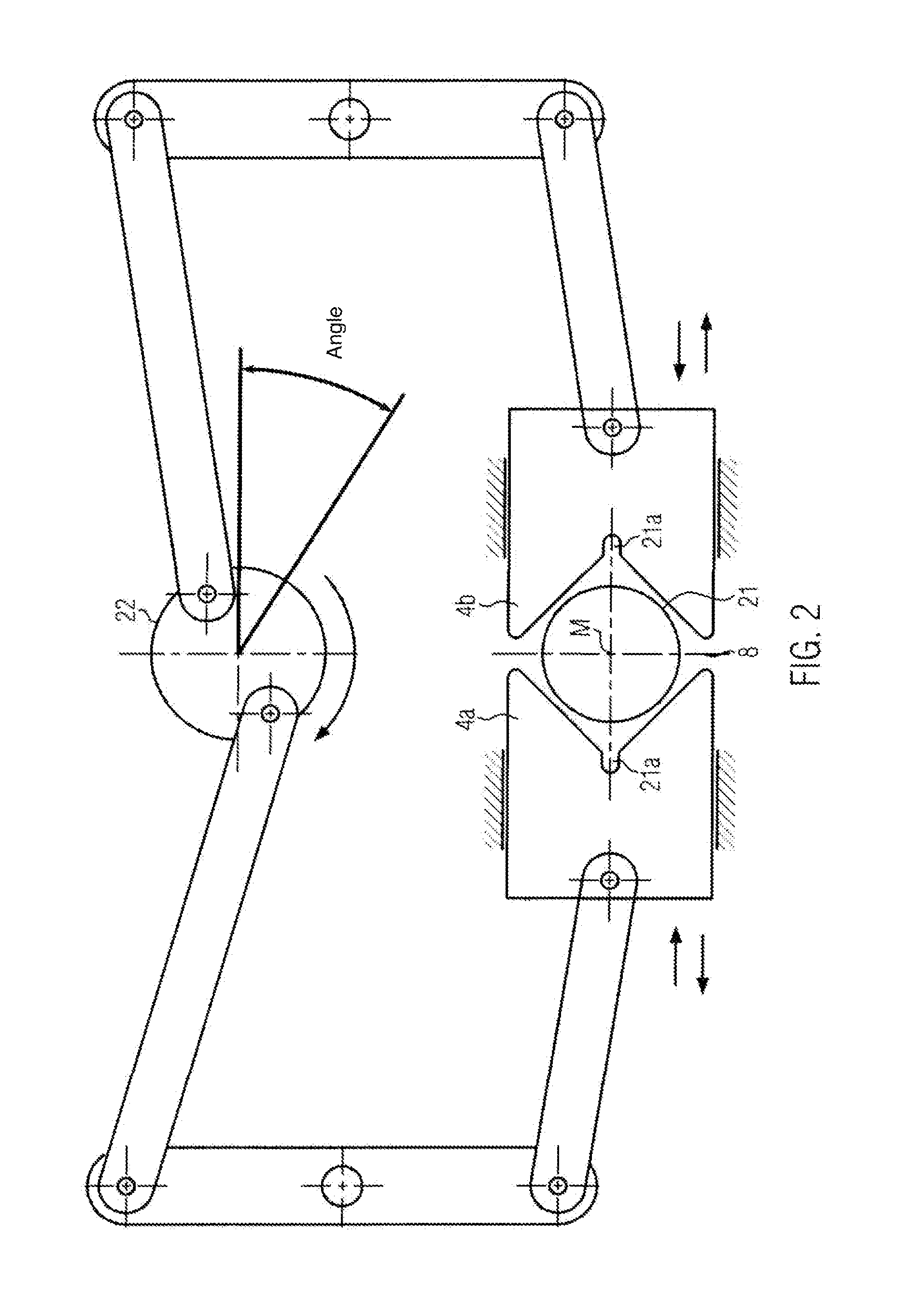
[0080 shows a smaller portion of, for example, 20 cm3, such that a shorter time tPortion results. In this case, the formula tClippause=tPortion−2×tClipstopp gives a value smaller than zero. This means that the clipper works in continuous operation with a passage speed Vpassage, i. e. the clipper scissors do not stand still. The passage speed Vpassage=f(t)Portion, tClipstopp), i e. the passage speed, results by the superposition of the functional sections, i. e. the ramps in the time segments tClipstopp and trise (tClipstopp=trise) with a given acceleration or deceleration. The intersecting point of the functional sections results in the passage speed.

[0081]The calculation of the clipper scissor speed is here one example. It is essential that tStart and tStopp′ are at the beginning and at the end of the portioning time tPortion′ and the position of the scissors at the times tStart and tStop are at least in a position≧PStart, preferably=PStart.

[0082]Thus, depending on the filling prof...


PUM


Abstract

A method and a device for controlling a filling machine with a clipping machine, the clipping machine and the filling machine exchanging process data via a communication interface, where functions of the clipping machine, in particular the movement profile of opposed clipper scissors, and functions of the filling machine, in particular the speed profile of a feed mechanism, are automatically adjusted with respect to each other by at least one control system.

Description

CROSS-REFERENCE TO RELATED APPLICATION[0001]The present application claims priority to European Application No. 13 160 903.4, filed Mar. 25, 2013. The priority application, EPO 13 160 903.4, is hereby incorporated by referenceFIELD OF THE DISCLOSURE[0002]The present disclosure relates to a method for controlling a filling machine with a clipping machine and a corresponding device.BACKGROUND[0003]In sausage production, it is known to separate a sausage length filled by a filling machine with so-called clipper scissors, wherein the pasty mass is displaced by the clipper scissors which move towards each other. Then, a so-called clip or double clip is inserted between the clipper scissors which closes the individual sausage portions. The sausages may then be cut through between the double clip.[0004]Sausage production with a clipping machine may be divided into the following process steps:[0005]1. Filling machine: A feed mechanism ejects a portion and stops after set volume is reached.[...

Claims


Application Information

Patent Timeline
IPC IPC(8): A22C11/02A22C11/12
CPCA22C11/125A22C11/02A22C11/0245A22C11/104
Inventor SCHMID, KLAUS
Owner ALBERT HANDTMANN MASCHFABRICK
Learn More