Ring seal installation tool

Inactive Publication Date: 2014-10-02
CATERPILLAR INC
View PDF11 Cites 5 Cited by
  • Summary
  • Abstract
  • Description
  • Claims
  • Application Information

AI Technical Summary

Problems solved by technology

Installation of a new sealing ring may be a time consuming process causing high machine-down time and affecting

Method used


Image

  • Ring seal installation tool
  • Ring seal installation tool
  • Ring seal installation tool

Examples


Example

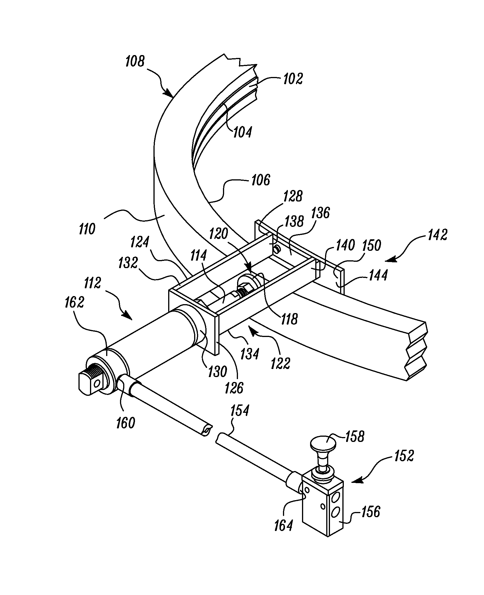
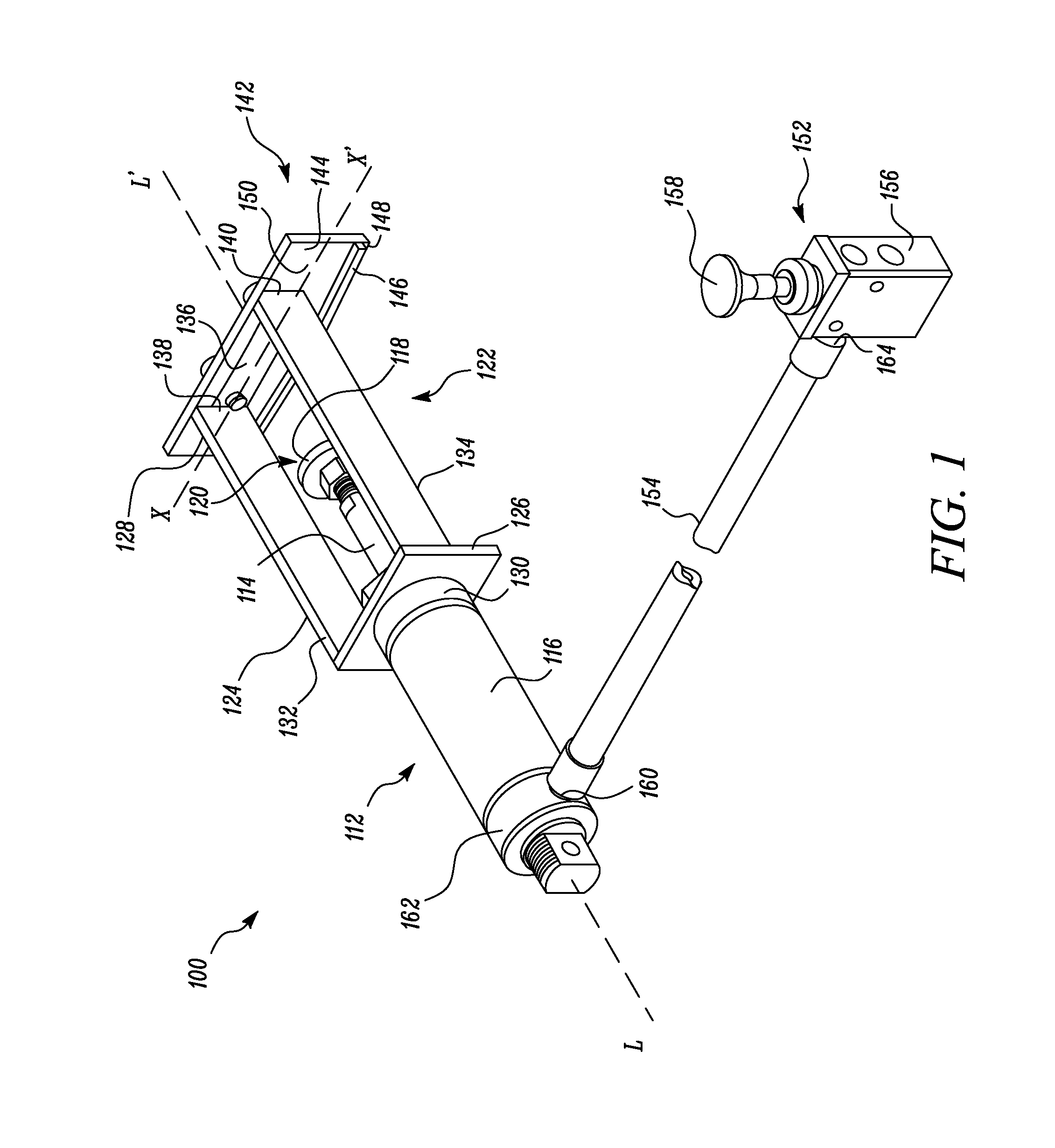
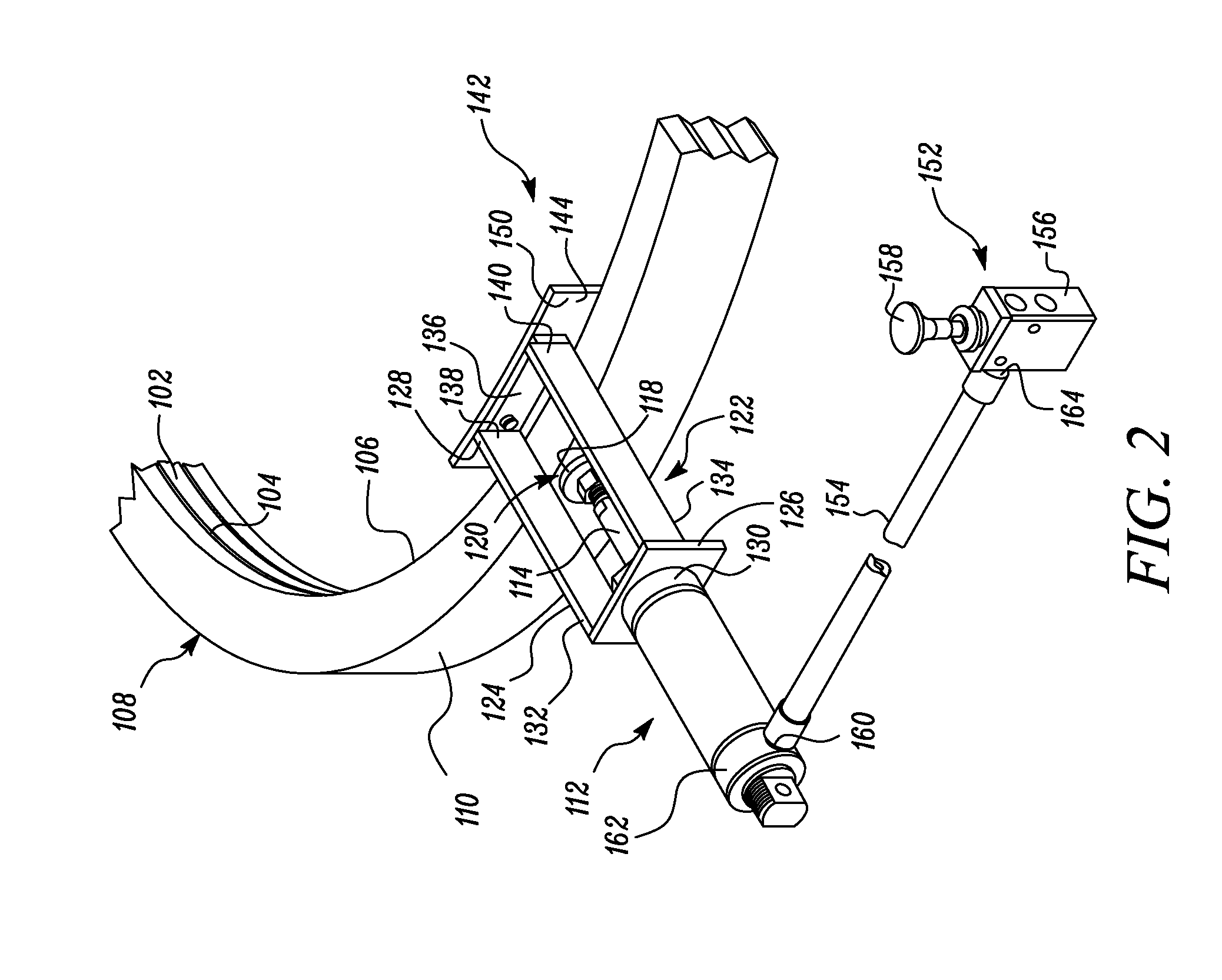
[0010]Wherever possible, the same reference numbers will be used throughout the drawings to refer to the same or the like parts. FIG. 1 illustrates a tool 100 for installing a ring seal 102 within a groove 104, according to one embodiment of the present disclosure. The tool 100 may include a rod and cylinder assembly 112. The rod and cylinder assembly 112 includes a rod 114 slidably received in a cylinder 116. The rod and cylinder assembly 112 further defines a longitudinal axis L-L′ along a centreline of the rod 114. The cylinder 116 may be a pneumatic or a hydraulic cylinder 116, and the rod 114 may act as a piston for the cylinder 116. In an exemplary embodiment, the cylinder 116 used is a pneumatically operated cylinder. Further, a stopper 118 may be coupled to a free end 120 of the rod 114. In an embodiment, the stopper 118 and the rod 114 may be manufactured as a unitary component. Alternatively, the stopper 118 and the rod 114 may be separate components. The rod 114 may be co...


PUM

PropertyMeasurementUnit
Diameteraaaaaaaaaa

Abstract

A tool for installing a ring seal within a groove is provided. The groove is disposed within an inner diameter of a flange. The flange has an outer flange portion extended radially outward from the groove. The tool includes a rod and cylinder assembly defining a longitudinal axis along a centerline of a rod of the rod and cylinder assembly. A trigger mechanism is coupled to the rod and cylinder assembly. A flange engagement assembly is attached to the rod and cylinder assembly. The flange engagement assembly includes a main frame having a first end attached to the rod and cylinder assembly and a second end aligned with and extended along the longitudinal axis. A seal installation attachment is removably attachable to the second end of the main frame and structured and arranged to selectively overlay the inner diameter of the flange.

Description

TECHNICAL FIELD[0001]The present disclosure relates to a tool, and more specifically to the tool for installing a ring seal in an internal groove of a housing.BACKGROUND[0002]Large diameter sealing rings may be utilized in association with gears of different machines. For example, in a hydraulic excavator, a sealing ring may be provided on an inner diameter of the swivel gear. Upon usage, the sealing ring may need to be replaced. Installation of a new sealing ring may be a time consuming process causing high machine-down time and affecting overall productivity. Further, sometimes it may be difficult to access the sealing ring due to space constraints. Hence, there is a need for providing an improved installation tool.[0003]U.S. Published Application Number 2011 / 0010930 (hereinafter referred as the '930 publication) discloses an apparatus for inserting a seal into a slewing bearing including a main body, a pressing unit, a pressure unit, an adjustment unit, and a guide unit. The main...

Claims


Application Information

Patent Timeline
IPC IPC(8): B25B27/00
CPCB25B27/0028B25B27/0092Y10T29/5383
Inventor RADHAKRISHNAN, ANUPAMBALFANZ, JAMES W.MILLER, STEVE J.SAMPATH, RAJESH
Owner CATERPILLAR INC
Why Eureka
Try Eureka