Impingement cooling mechanism, turbine blade and combustor

a cooling mechanism and turbine blade technology, applied in the direction of lighting and heating apparatus, vessel construction, marine propulsion, etc., can solve the problems of affecting the cooling effect of the blade, and achieve the effect of increasing the cooling effect by impingement, effective utilization of cooling gas, and increasing the heat transfer coefficien

Active Publication Date: 2014-10-02
IHI CORP
View PDF44 Cites 22 Cited by
  • Summary
  • Abstract
  • Description
  • Claims
  • Application Information

AI Technical Summary

Benefits of technology

[0017]According to the present invention, the blocking members that block the crossflow are disposed on at least the upstream side of the crossflow with respect to the impingement holes. For this reason, intrusion of the crossflow into the region between the impingement holes and the cooling target is inhibited. Accordingly, most of the cooling gas that is ejected from the impingement holes collides with (reaches) the cooling target without being influenced by the crossflow, and so the cooling effect by the impingement cooling increases.
[0018]Also, the turbulent flow promoting portions are provided in the flow path of the crossflow that is regulated by the blocking members. Accordingly, by disturbing the flow of the crossflow by the turbulent flow promoting portions, it is possible to increase the heat transfer coefficient between this crossflow and the cooling target.
[0019]Therefore, according to the present invention, it is possible to effectively utilize cooling gas of a limited flow rate that is supplied from the impingement holes, and further increase the cooling effect by the impingement cooling.

Problems solved by technology

However, when a crossflow is formed between the impingement plate and the blade main body, the cooling gas that is ejected from the impingement holes positioned on the downstream side of this crossflow ends up being swept into (entrained into) the crossflow, and therefore hindered from reaching the blade main body.

Method used


Image

  • Impingement cooling mechanism, turbine blade and combustor
  • Impingement cooling mechanism, turbine blade and combustor
  • Impingement cooling mechanism, turbine blade and combustor

Examples


first embodiment

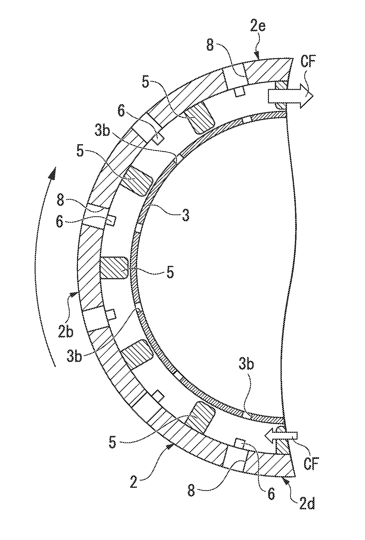
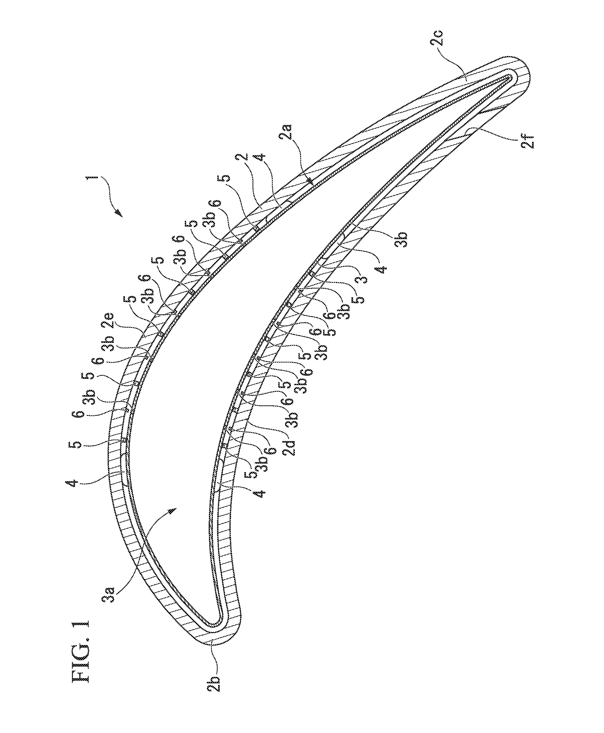
[0033]FIG. 1 is a cross-sectional view that shows the outline configuration of a turbine blade having the impingement cooling mechanism of the present embodiment. A turbine blade 1 is provided with a blade main body 2 and an impingement plate 3.

[0034]The blade main body 2 forms the outer shape of the turbine blade 1, and has therein a space (interior space) 2a, and the blade main body 2, which serves as the cooling target in the impingement mechanism, is provided with a leading edge portion (blade leading edge portion) 2b, a trailing edge portion (blade trailing edge portion) 2c, a front-side blade surface (blade front) 2d, and a back-side blade surface 2e. Also, a through-hole 2f that penetrates from the interior space 2a to the outer portion of the blade main body 2 is formed at the trailing edge portion 2c.

[0035]The impingement plate 3 has an analogous outer shape approximately equivalent to the outer shape of the interior space 2a of the blade main body 2, and functions as a fa...

second embodiment

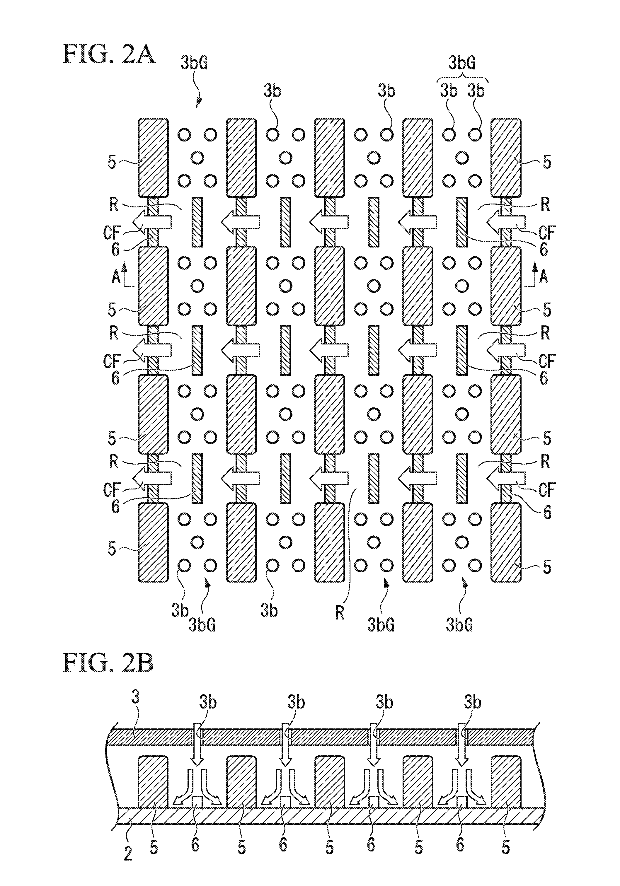
[0051]FIG. 3A and FIG. 3B are drawings for describing the turbine blade that has the impingement cooling mechanism of the present embodiment. FIG. 3A is a plan view that schematically shows the main portions of the inner surface side of the blade main body 2 (that is to say, a plan view that shows the outline configuration of the impingement cooling mechanism). Also, FIG. 3B is a cross-sectional view along A-A line of FIG. 3A.

[0052]The point of difference between the turbine blade (impingement cooling mechanism) of the present embodiment and the turbine blade (impingement cooling mechanism) shown in FIG. 2A and FIG. 2B is the point of the sizes of the blocking plate 5 and the turbulent flow promoting portion 6 not being uniform, and differing along the flow direction of the crossflow CF.

[0053]In contrast, the width of the blocking plate 5 that is arranged on the upstream side of the impingement hole group 3bG is relatively wider on the upstream side of the crossflow CF, and relative...

third embodiment

[0057]FIG. 4A and FIG. 4B are drawings for describing a turbine blade that has the impingement cooling mechanism of the present embodiment. FIG. 4 is a plan view that schematically shows the main portions of the inner surface side of the blade main body 2 (that is to say, a plan view that shows the outline configuration of the impingement cooling mechanism). Also, FIG. 4B is a cross-sectional view along A-A line of FIG. 4A.

[0058]The point of difference between the turbine blade (impingement cooling mechanism) of the present embodiment and the turbine blade (impingement cooling mechanism) shown in FIG. 2A and FIG. 2B is the point of the impingement holes 3b being arranged in the flow path R of the crossflow CF that is regulated by the blocking plates 5. That is to say, in the present embodiment, an in-flow-path impingement hole group G1 that consists of four of the impingement holes 3b is formed in the flowpath between the impingement hole groups 3bG; 3bG. The blocking plates 5 are n...


PUM


Abstract

The present invention relates to an impingement cooling mechanism that ejects a cooling gas toward a cooling target (2) from a plurality of impingement holes (3b) formed in a facing member (3) that is disposed facing the cooling target (2). Blocking members (5) that block a crossflow (CF), which is a flow formed by the cooling gas after being ejected from the impingement holes (3b), are installed on at least the upstream side of the crossflow (CF) with respect to at least a portion of the impingement holes (3b). Turbulent flow promoting portions (6) are provided in the flow path (R) of the crossflow (CF) regulated by the blocking members (5).

Description

TECHNICAL FIELD[0001]The present invention relates to an impingement cooling mechanism, a turbine blade and a combustor.[0002]This application is a Continuation of International Application No. PCT / JP2012 / 082569, filed on Dec. 14, 2012, claiming priority based on Japanese Patent Application No. 2011-274878, filed Dec. 15, 2011, the content of which is incorporated herein by reference in their entity.BACKGROUND ART[0003]In turbine blades and combustors exposed to high-temperature environments, cooling is performed in order to inhibit a reduction in service life due to thermal damage. As a cooling mechanism that performs such cooling, an impingement cooling mechanism is often employed in the case of, for example, low pressure loss of a turbine nozzle or the like being required in a turbine blade. In an impingement cooling mechanism in a turbine blade, a hollow impingement plate in which a plurality of impingement holes are formed is installed in the interior of the turbine blade. Blow...

Claims


Application Information

Patent Timeline
Patent Type & Authority Applications(United States)
IPC IPC(8): F01D5/18F23R3/00
CPCF01D5/189F05D2260/201F05D2260/2212F23R3/002F23R2900/03044F01D5/187F05D2260/22141Y02T50/60
Inventor FUJIMOTO, SHUNAKAMATA, CHIYUKIOKITA, YOJI
Owner IHI CORP
Why Eureka
Try Eureka