Bio-imaging method and system

a bio-imaging and system technology, applied in the field of bio-imaging methods and systems, can solve the problems of inability to model microorganism growth and find automated systems, human error and inconsistency, and inability to carry out preliminary analysis,

Active Publication Date: 2014-10-02
BIOMERIEUX SA
View PDF2 Cites 19 Cited by
  • Summary
  • Abstract
  • Description
  • Claims
  • Application Information

AI Technical Summary

Benefits of technology

[0023]Optionally, the directions of at least two of the illumination sources are substantially not coplanar. In one embodiment, the largest angle of intersection between the directions of the at least two illumination sources is less than 170°, optionally less than 160°, optionally less than 150°. Using at least two illumination sources whose respective directions are substantially not coplanar allows improved identification and detection of objects, marks and characteristics of the objects.
[0028]Using at least two or three illumination sources of different types (such as a backlighting source, a near horizontal source, etc.) also allows improved identification and detection of objects, marks and characteristics of the objects.
[0064]combining first and second images based on an fusion algorithm to apply different weights to different image characteristics to produce a color image having contour information making it possible to detect a and / or 13 hemolysis.

Problems solved by technology

The preliminary visual analysis works well, but is prone to human error and inconsistency due to the huge diversity of shapes, colors, sizes and forms of the different microorganisms which may be difficult to interpret.
In addition, as much of the growth is “random”, it is not easy to model microorganism growth and find automated systems which lend themselves to the diversity identified above.
Indeed, it is stated in both US2004 / 0101951 and US2010 / 0232660 that “some biological growth plates may require only front or back illumination, but not both.” Such illumination is basic and does not allow images that have sufficient quality to carry out a preliminary analysis in an efficient manner to be obtained.
However, there are many problems associated with enhancing images of biological samples.
Many of these problems can only be solved by bespoke applications.

Method used


Image

  • Bio-imaging method and system
  • Bio-imaging method and system
  • Bio-imaging method and system

Examples


Embodiment Construction

[0095]The present invention relates to a system for analyzing biological specimens in a fully or semi automated manner. In the present description, the term ‘object’ relates to a real object such as bubbles or colonies, the term ‘mark’ relates to a characteristic of a vessel such as an artifact or a serigraphy, and the term ‘feature’ relates to a characteristic of an object. In addition, the term ‘Petri plate’ defines an assembly of a Petri dish and a lid to cover the Petri dish.

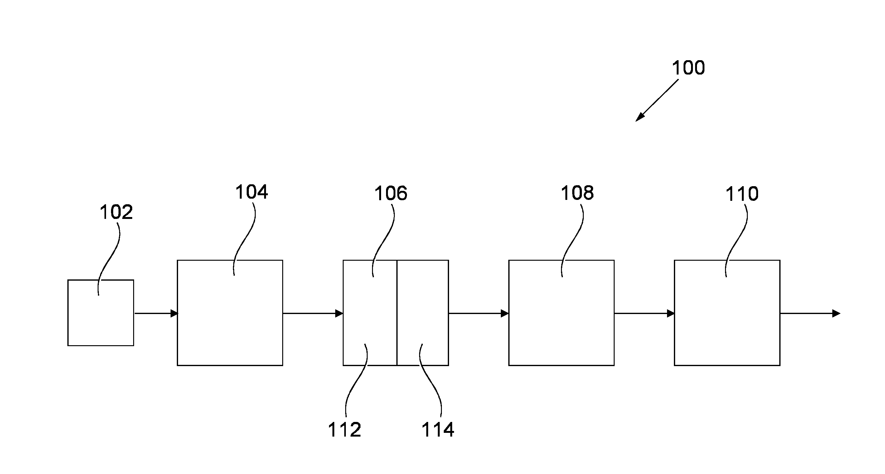
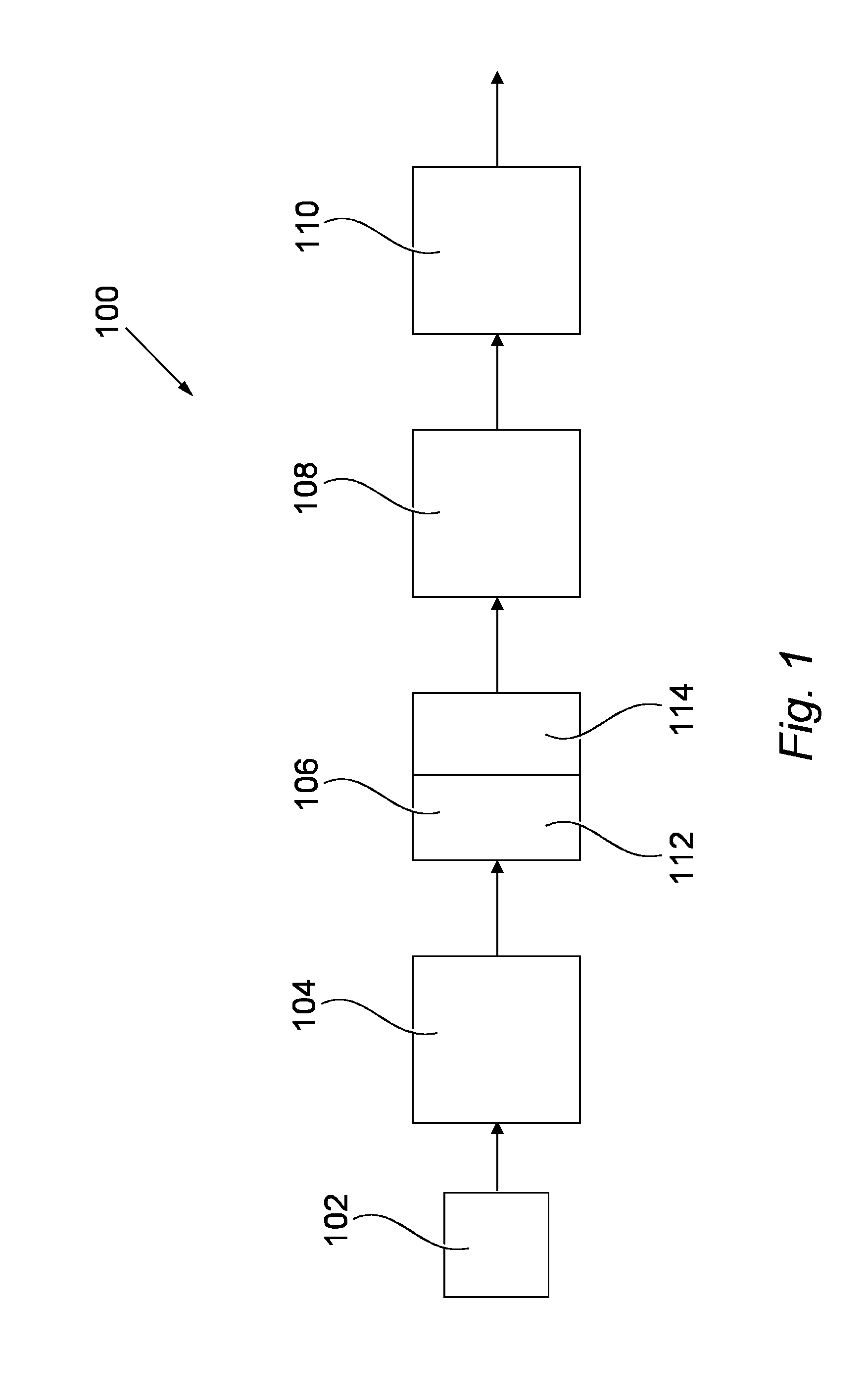
[0096]FIG. 1 shows an example of a system 100 according to the present invention.

[0097]The system 100 includes a sample vessel bank 102, an automatic streaking machine 104, a smart incubator system 106, a processing unit 108 and an identification system 110.

[0098]The sample bank 102 produces manually or automatically sample vessels into which biological samples can be grown and analyzed. The sample vessel is typically a Petri dish, although other vessels may also be used. Accordingly, reference to a Petri di...


PUM

PropertyMeasurementUnit
angleaaaaaaaaaa
angleaaaaaaaaaa
angleaaaaaaaaaa

Abstract

An imaging system for generating images of biological samples having a surface, the system comprising: a sample support for supporting a biological sample in use; a plurality of illumination sources, the plurality of illumination sources being arranged around the sample support and each adapted to illuminate the biological sample, in use, from a different direction; an image capture device for capturing illumination which has impinged on the biological sample to thereby form an image of the sample; wherein at least one of the illumination sources direction is not perpendicular to the surface of the sample.

Description

FIELD OF THE INVENTION[0001]The present invention relates to a method and system for analyzing in vitro samples.BACKGROUND OF THE INVENTION[0002]In vitro analysis is carried out in many environments in order to identify biological samples such as microorganisms, cell and tissue cultures, cellular or sub-cellular extracts, and purified molecules. Samples of various materials are isolated from their usual biological context and provided with an environment in which they can grow. This environment is often provided in the form of a Petri dish which is placed into an incubator in order for the samples to grow. The Petri dish normally includes a microbiological culture medium which encourages growth of the sample. Ideally, incubation on an appropriate culture medium gives rise to the growth of a number of colonies of the sample. Subsequent analysis of the colonies is generally carried out to identify the microorganisms and assess their sensitivity or resistance to antimicrobials.[0003]An...

Claims


Application Information

Patent Timeline
Patent Type & Authority Applications(United States)
IPC IPC(8): G01N21/01G01N21/25G01N21/27G01N21/17
CPCG01N21/255G01N21/17G01N2201/0626G01N21/01G01N21/27G06T7/0012G06V20/69G06V20/693
Inventor DDECAUX, DOMINIQUEPINSTON, FREDERICDESSEREE, DENISBOISSIER, GUILLAUMETACHIER, CHRISTOPHEFULCHIRON, CORINELAPIERRE, LORETTEALLANO, LORENEJACOLIN, LEONTINE
Owner BIOMERIEUX SA
Why Eureka
Try Eureka