Compensation Of Optical Aberrations Caused By Non-Planar Windows

Active Publication Date: 2014-10-02
NOKIA TECHNOLOGLES OY
View PDF7 Cites 3 Cited by
  • Summary
  • Abstract
  • Description
  • Claims
  • Application Information

AI Technical Summary

Benefits of technology

[0004]In accordance with one aspect, an example apparatus comprises at least one optical window having a non-planar front surface which causes aberration of an input image; and a diffractive element comprising a plurality of Fresnel zones configured to correct the aberration of the input image and located on a back surface of the at least one optical window or between the back surface and a sensor image plane where the input image is focused on. The aberration is corrected to be below predefined one or more parameters for the input image and for each wavelength of the input image for which the aberration caused by the non-planar front surface was above the predefined one or more parameters.
[0005]In accordance with another aspect, an example method, comprises receiving an

Problems solved by technology

Non-planar optical windows such as curved glass windows can make many electronic/imaging devices look beautiful and are widely used as a marketing tool, so that flat optical windows may be undesirable from that point of view.
Unfortunately, curved surfaces of these optical windows with a high

Method used


Image

  • Compensation Of Optical Aberrations Caused By Non-Planar Windows
  • Compensation Of Optical Aberrations Caused By Non-Planar Windows
  • Compensation Of Optical Aberrations Caused By Non-Planar Windows

Examples


Example

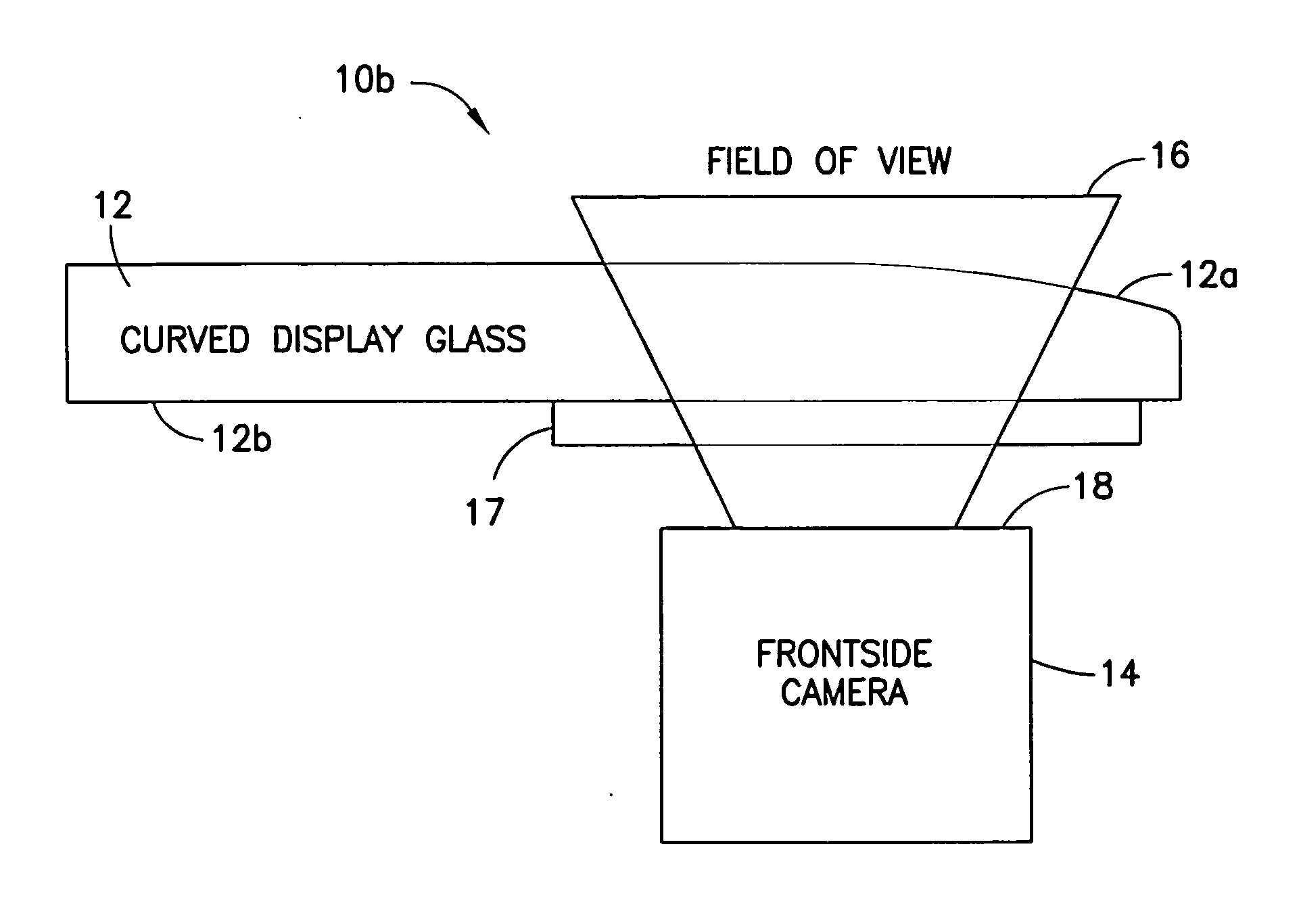
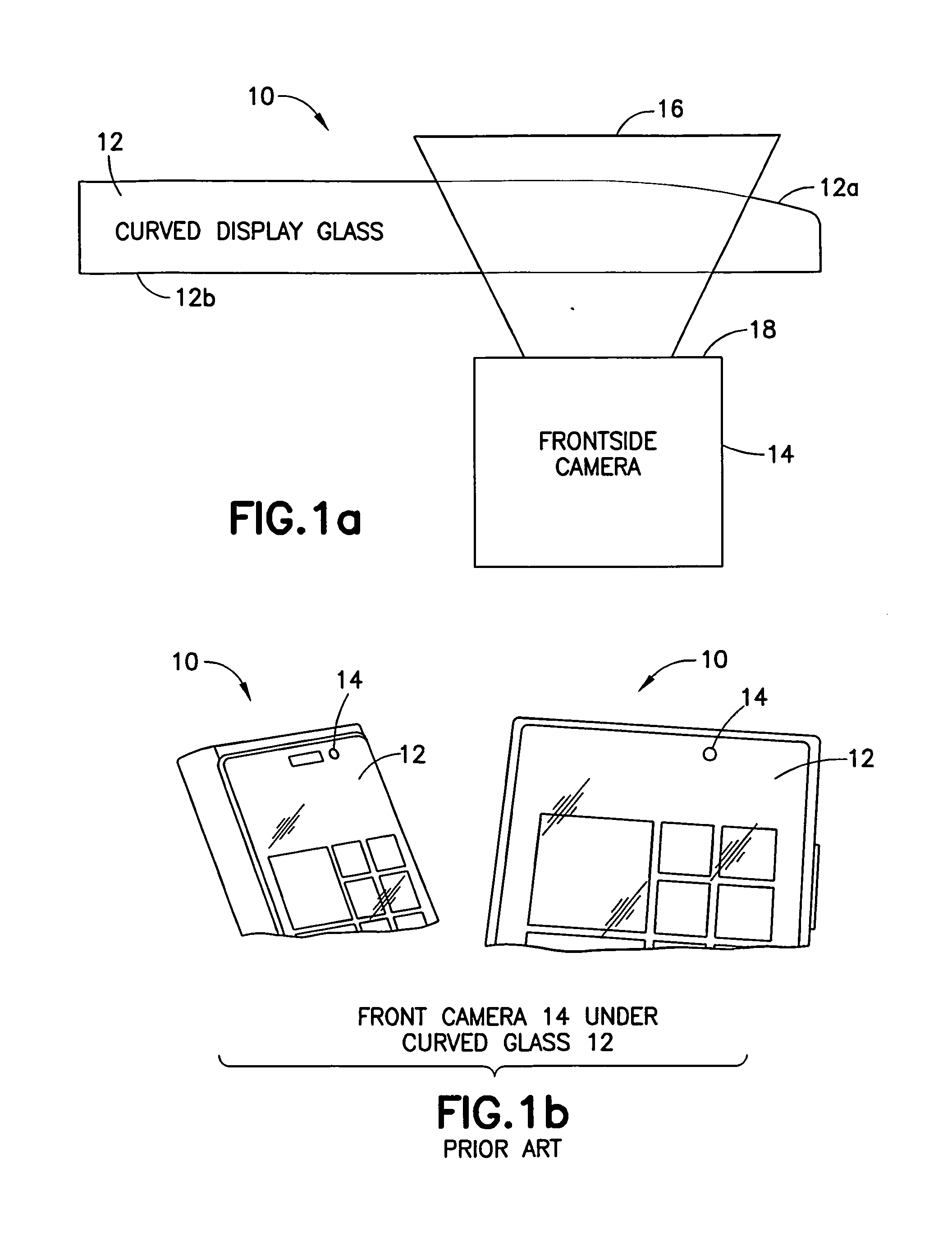
[0018]FIGS. 1a and 1b demonstrate an electronic device 10 comprising a curved optical window 12 (having a curved surface 12a and a flat surface 12b) in front of a camera / sensor 14. The curved portion 12a of the optical window 12 may cause aberrations of the input image 16 focused on a camera / sensor image plane 18. As shown in FIG. 1a, a single side curved glass on the top of the camera 14 can act as a lens blurring an image at least in one direction by moving a focal point at least in one direction for example, due to a refractive power of the curved optical surface 12a.

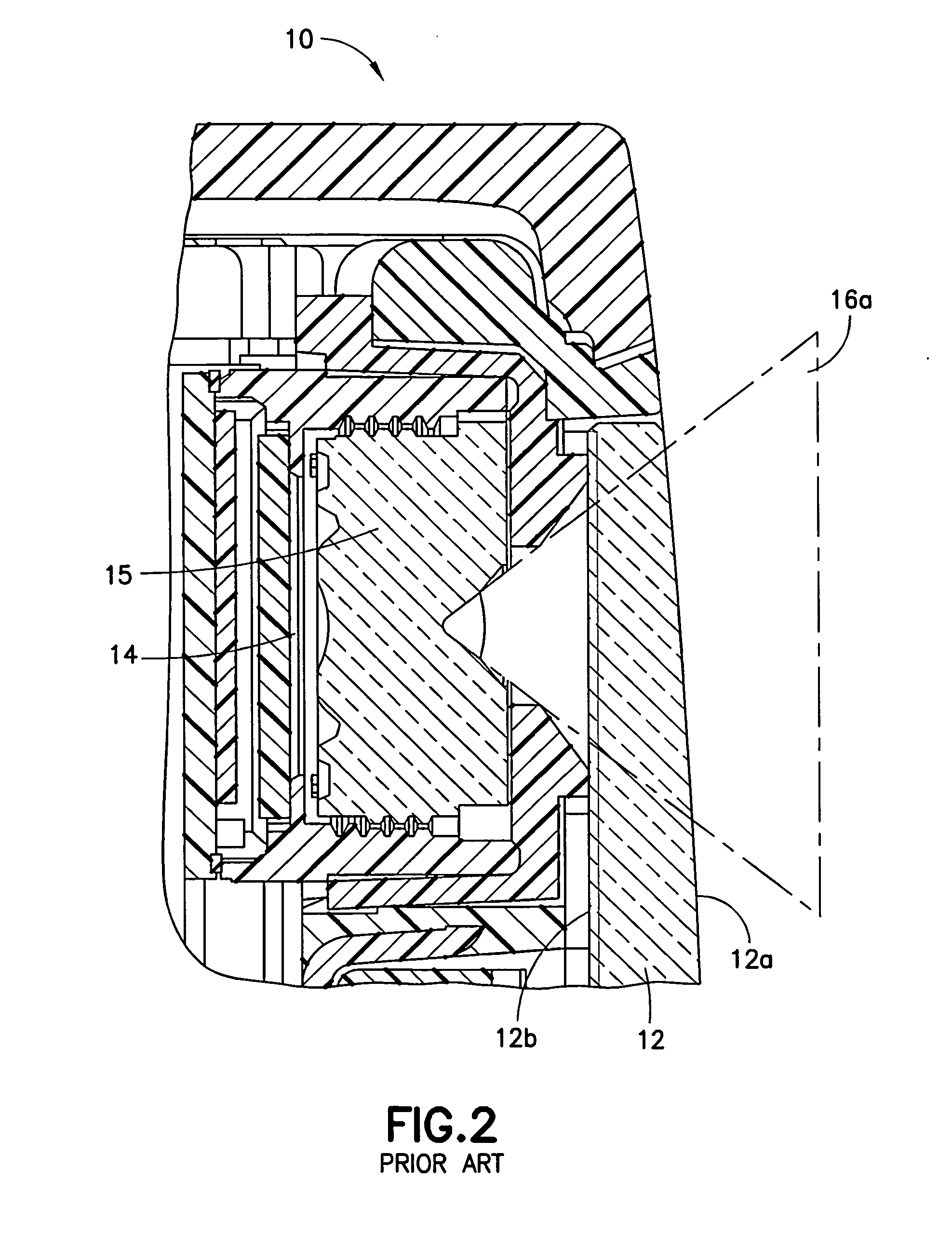
[0019]FIG. 2 shows a more detailed schematic picture of an exemplary electronic device 10a (similar to the device 10) comprising a curved optical window 12 (having a curved surface 12a and a flat surface 12b). The curved surface 12a can have a variable curvature towards one direction at the surface (for example with radius of curvature of 64.21 mm, 86.48 mm and 136.17 mm at different points / positions at the surface ...


PUM


Abstract

The specification and drawings present a new apparatus and a new apparatus for compensation of the optical aberrations caused by a non-planar window (or windows in general, for example windows having a curved surface) using a diffractive (optical) element such as a diffractive foil in electronic/camera devices such as electronic devices with displays. According to an embodiment, an optical window of an electronic device/camera may have at least a non-planar front surface which causes an aberration of an input image. This aberration can be corrected to be below predefined one or more parameters (such as a circle with a predefined maximum radius and/or a directional shift by a predefined maximum value) using a diffractive element/foil located on/near a back surface of the optical window or between the back surface of the optical window and a sensor/camera image plane where the input image is focused on.

Description

TECHNICAL FIELD[0001]The exemplary and non-limiting embodiments relate generally to electronic devices with displays and more specifically to compensation of optical aberrations caused by non-planar window(s) in an electronic / optical / camera device.BACKGROUND ART[0002]This section is intended to provide a background or context to the invention disclosed below. The description herein may include concepts that could be pursued, but are not necessarily ones that have been previously conceived. implemented or described. Therefore, unless otherwise explicitly indicated herein, what is described in this section is not prior art to the description in this application and is not admitted to be prior art by inclusion in this section.[0003]Non-planar optical windows such as curved glass windows can make many electronic / imaging devices look beautiful and are widely used as a marketing tool, so that flat optical windows may be undesirable from that point of view. Unfortunately, curved surfaces o...

Claims


Application Information

Patent Timeline
IPC IPC(8): G02B5/18
CPCG02B5/1895G02B5/189G02B27/4216
Inventor JUHOLA, MIKKO A.PARIKKA, MARKO K.WRIGHT, ANTTI I.HAIKKA, TIMO J.HAUTALA, MIKKO T.
Owner NOKIA TECHNOLOGLES OY
Why Eureka
Try Eureka