

Battery cooling structure
a battery and cooling structure technology, applied in the field of battery cooling structure, can solve the problems of increasing the cost of the heat conduction sheet, disadvantageous in the cost of providing the heat conduction sheet, etc., and achieve the effect of reducing the cost of the heat conduction member and ensuring the cooling capability of the battery
- Summary
- Abstract
- Description
- Claims
- Application Information
AI Technical Summary
Benefits of technology
Problems solved by technology
Method used
Image

Examples
first embodiment
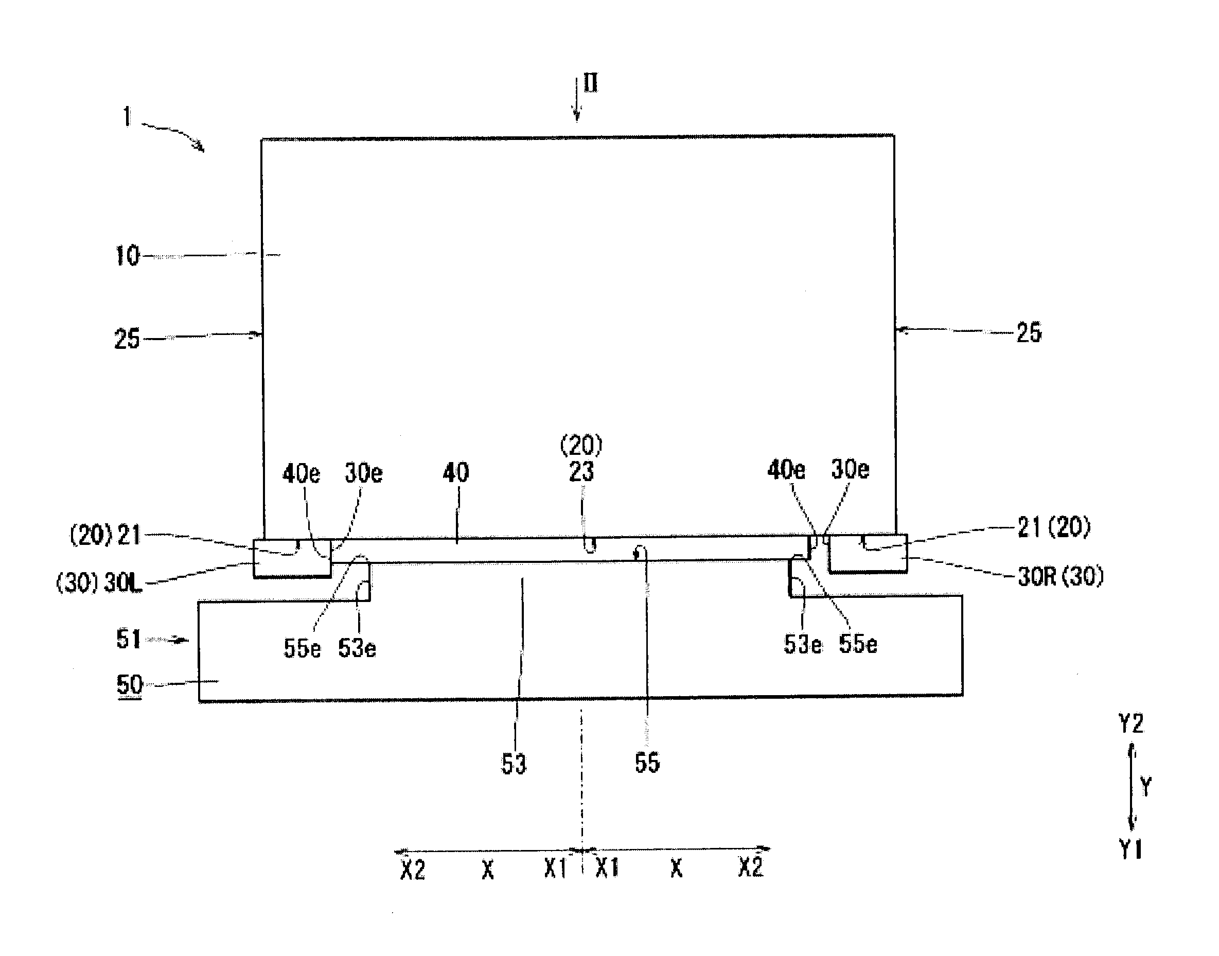
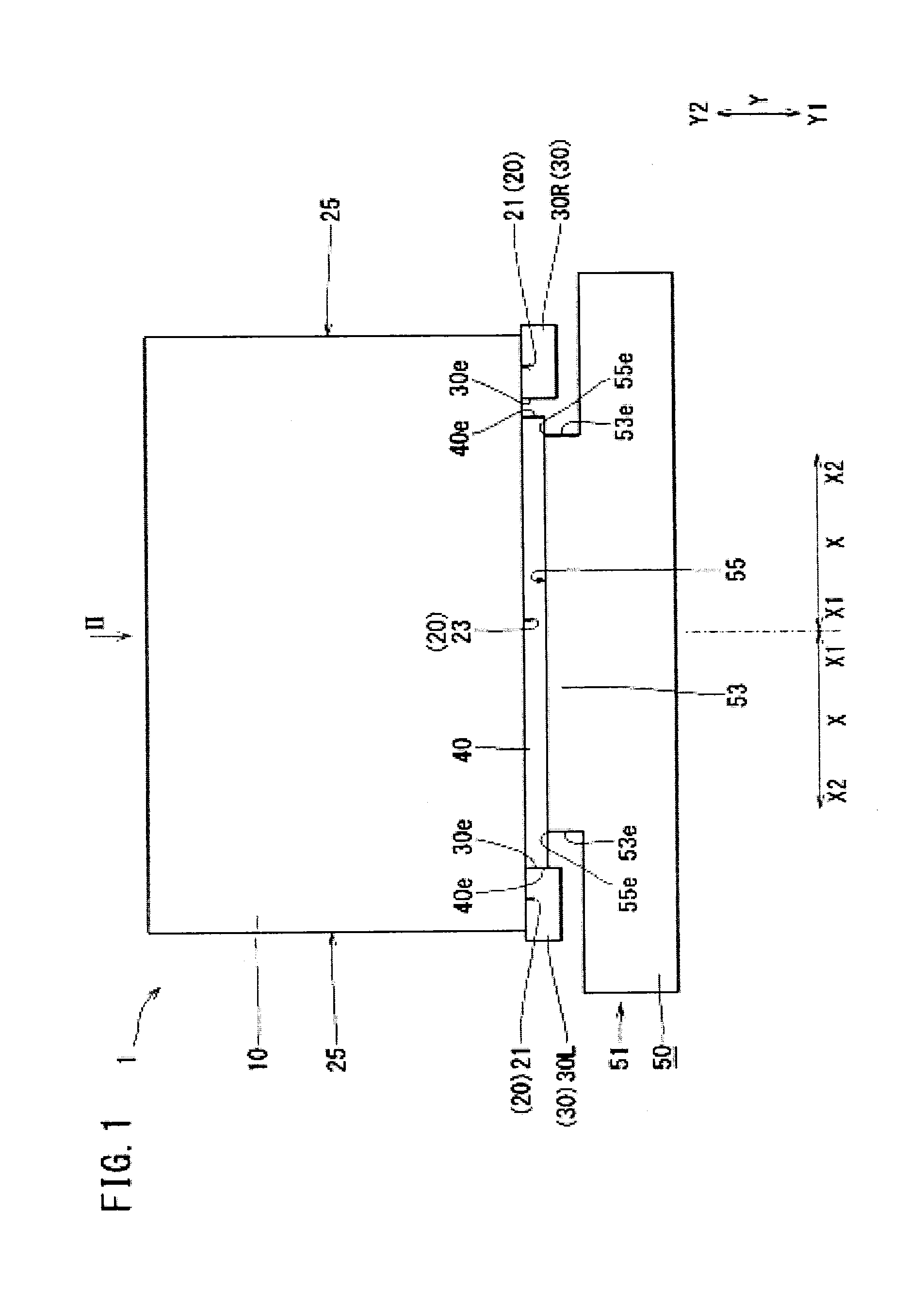
[0016]A battery cooling structure 1 of First Embodiment will be described with reference to FIG. 1 and FIG. 2.
[0017]The battery cooling structure 1 is a structure for cooling (adjusting the temperature of) a battery 10 shown in FIG. 1. The battery cooling structure 1 is provided, for example, in a vehicle. An example of the vehicle is a working vehicle, and an example of the working vehicle is an excavator. Examples of the excavator include a hybrid excavator (which utilizes an engine power and an electric power) and an electric excavator. The battery cooling structure 1 includes a battery 10, a supporter 30, a heat conduction member 40, and a heat sink 50.
[0018]The battery 10 is, for example, a storage battery. The battery 10 generates heat when it is charged or discharged. The battery 10 is, for example, rectangular parallelepiped in shape. The surfaces of the battery 10 include a battery heat transfer surface 20 and side surfaces 25.
[0019]The battery heat transfer surface 20 is a...
second embodiment
[0067]Referring to FIG. 3 and FIG. 4, differences between a battery cooling structure 201 of Second Embodiment and the battery cooling structure 1 (see FIG. 1) of First Embodiment will be described. The differences lie in a supporter 230C, a protrusion 253L, a protrusion 253R, a heat conduction member 240L, and a heat conduction member 240R. These differences will be further described below.
[0068]The supporter 230C is provided between the supporter 30L and the supporter 30R. For example, one supporter 230C is provided at the central part of the battery heat transfer surface 20 in the battery width direction X. The number of the supporters 230C may be two or more (hereinafter, the number of the supporters 230C is assumed to be one). In connection with the above, in the supporter non-contact part 23, a part between the supporter 30L and the supporter 230C will be referred to as a supporter non-contact part 223L whereas a part between the supporter 30R and the supporter 230C will be re...
third embodiment
[0072]Referring to FIG. 5, a difference between a battery cooling structure 301 of Third Embodiment and the battery cooling structure 1 (see FIG. 1) of First Embodiment will be described. The difference lies in the positions of the edges 40e of the heat conduction member 40. The difference will be further described below.
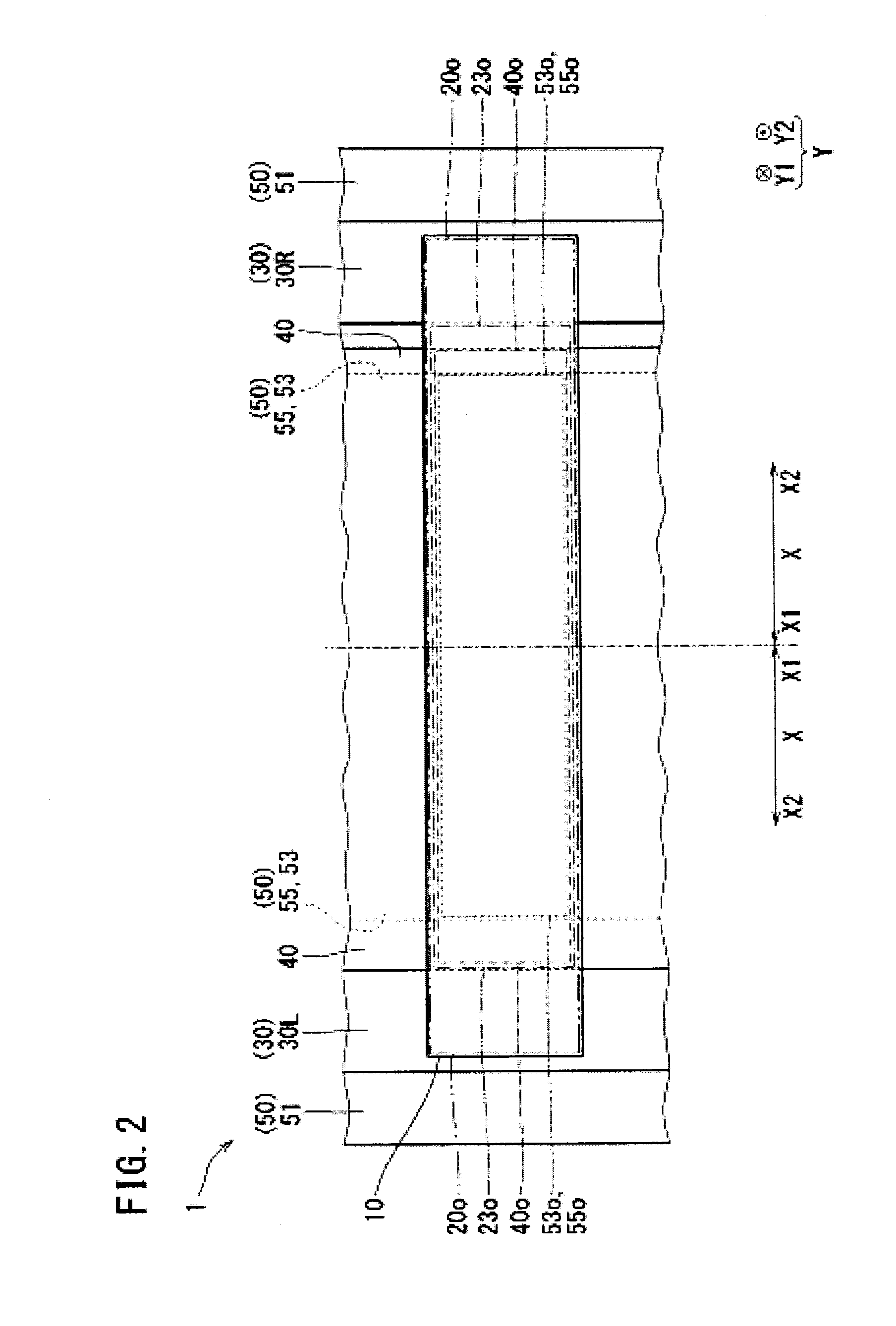
[0073]The heat conduction member 40 is disposed to be successive (without any gaps) between a position P1 and a position P2 which are described below. The position P1 locates between the protrusion heat transfer surface 55 and the supporter non-contact part 23. The position P1 is a part of the heat conduction member 40 which part contacts with (is sandwiched between) the protrusion heat transfer surface 55 and the supporter non-contact part 23. The position P2 locates between the main body 51 of the heat sink 50 and the supporter 30. As the heat conduction member 40 is disposed at the position P2, there are regions A where the supporters 30 overlap the heat conducti...
PUM
| Property | Measurement | Unit |
|---|---|---|
| heat conduction | aaaaa | aaaaa |
| height | aaaaa | aaaaa |
| insulating | aaaaa | aaaaa |
Abstract
Description
Claims
Application Information