
Mounted electrical receptacle

a technology of electrical receptacles and mounting brackets, which is applied in the direction of electrical equipment, domestic applications, coupling device connections, etc., can solve the problems of high cost of providing assemblies of outlets with different configurations, within a single assembly, etc., and achieves the effect of reducing the amount and/or cost of tooling, and being easy to configure or reconfigur

Active Publication Date: 2014-10-02
BYRNE NORMAN R
View PDF9 Cites 14 Cited by
  • Summary
  • Abstract
  • Description
  • Claims
  • Application Information

AI Technical Summary

Benefits of technology

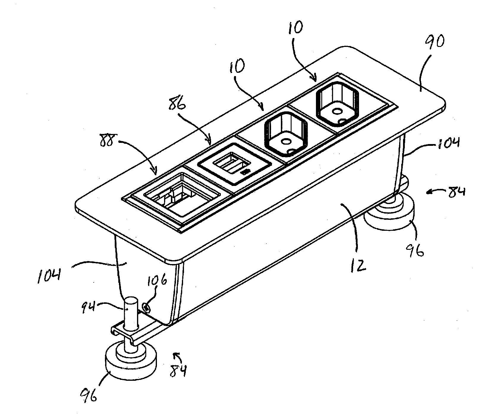
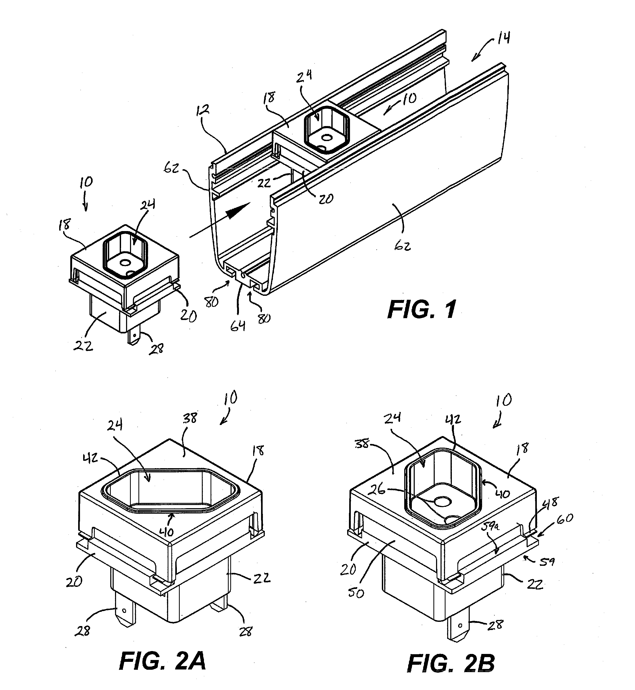
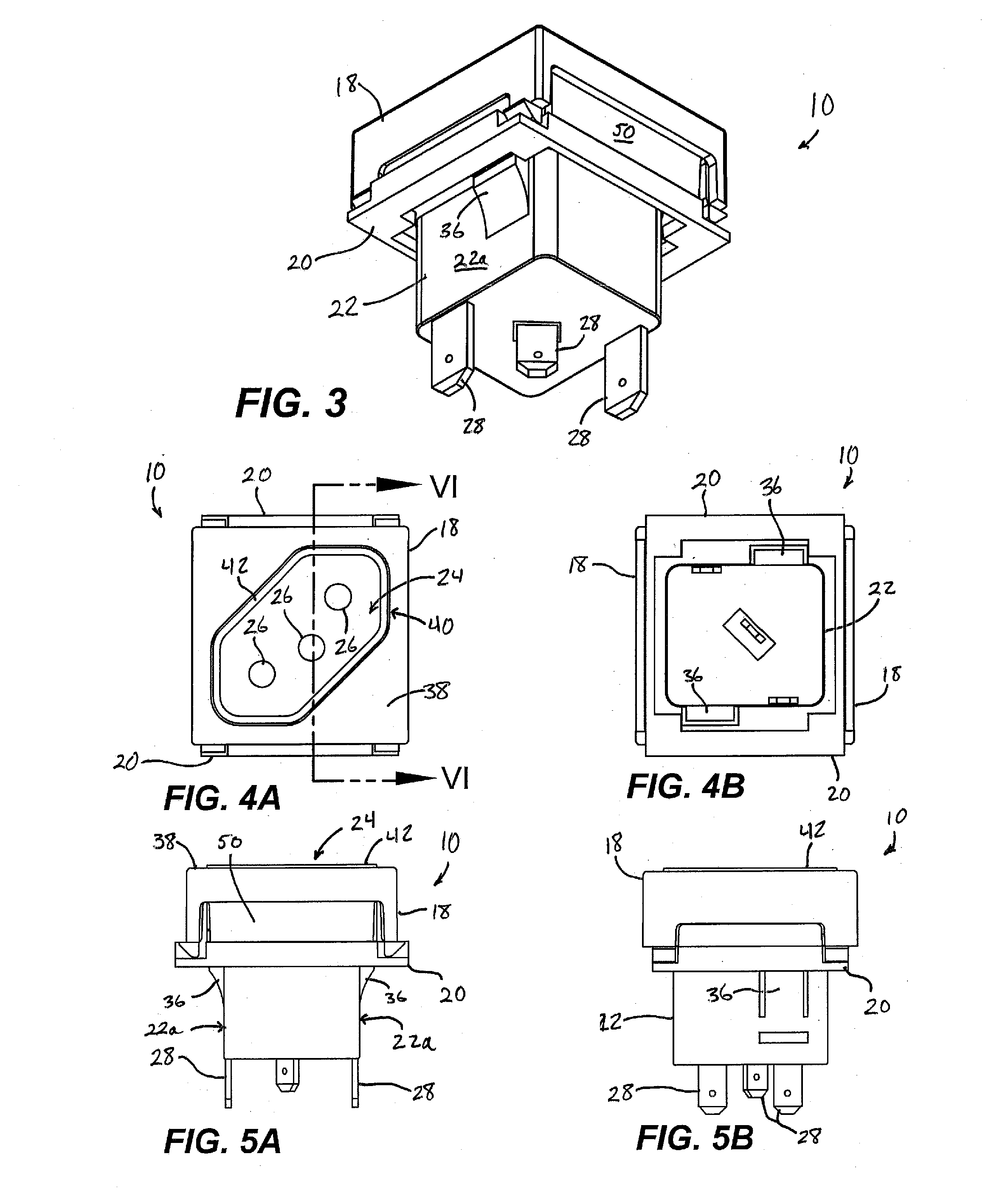
The present invention provides an electrical receptacle assembly that can be easily reconfigured to have different types and quantities of high or low voltage power receptacles and data outlets without needing to change the overall center. This allows for the construction of a readily-configurable or reconfigurable power center that can provide substantially any number of different styles or configurations of electrical receptacles and data outlets at a single location while reducing the number of parts needed to achieve many different configurations. The finished power center may be installed at or near a work surface, for example, and may be reconfigured as needed without replacing a large number of costly parts in order to do so.

Problems solved by technology

While it is often helpful or desirable to provide one or more electrical power outlets (and / or low voltage power outlets or data outlets, or combinations thereof) along or within reach of a work surface, such as a desk, a table, or the like, providing assemblies of outlets with different configurations, within a single assembly, can be costly due to the large number of variations that may need to be accommodated for a given application, in order to meet widely variable customer or consumer demands.

Method used


Image

  • Mounted electrical receptacle
  • Mounted electrical receptacle
  • Mounted electrical receptacle

Examples


Embodiment Construction

[0033]A mounted electrical receptacle is provided for use with a power receptacle support that is typically coupled to (or mounted near) a work surface such as a table, a desk, or the like. It is generally desirable that the number and type of receptacles at a given power receptacle support be variable according to the needs of a particular user or work area. For example, users may have need for one or more high voltage (e.g., 110V or 220V AC) standard power outlets, one or more low voltage power outlets (e.g., USB charging ports rated at about 2V to 6V DC), one or more electronic data ports (e.g., telephone, Ethernet, audio, video, etc.), as well as access to power or data cables near the work surface.

[0034]To maximize configurability for different markets around the world, which use many different styles of electrical outlets, it is advantageous to provide a common mechanical interface for substantially any number of different electrical receptacles to be mounted to a power recept...


PUM


Abstract

An electrical receptacle assembly is reconfigurable to provide any number of different styles or configurations of high or low voltage electrical receptacles and / or data outlets. The receptacle assembly includes a main body with an outlet receptacle portion, a flange portion extending outwardly from the main body, an upper frame member positioned generally above the flange portion, and a lower frame member positioned generally below the flange portion. A plurality of electrical contacts are positioned in the main body, and are configured to make electrical contact when the outlet receptacle portion receives an electrical or data plug associated with an electrical device. The upper and lower frame members are configured to interchangeably receive different main bodies with different outlet portions, and enable the different outlet portions to be mounted at a power center along a work surface or the like.

Description

CROSS REFERENCE TO RELATED APPLICATION[0001]The present application claims the benefit of U.S. Provisional Application, Ser. No. 61 / 807,491, filed Apr. 2, 2013, which is hereby incorporated herein by reference in its entirety.FIELD OF THE INVENTION[0002]The present invention relates to electrical power and data outlets or receptacles and, more particularly, to outlets and receptacles that are made accessible at a work surface such as a table or desk.BACKGROUND OF THE INVENTION[0003]Electrical power outlets and corresponding electrical plugs vary widely throughout the world, with many different shapes and electrical contact configurations in use. Even individual countries are known to have different configurations of outlets. While it is often helpful or desirable to provide one or more electrical power outlets (and / or low voltage power outlets or data outlets, or combinations thereof) along or within reach of a work surface, such as a desk, a table, or the like, providing assemblies...

Claims


Application Information

Patent Timeline
IPC IPC(8): H01R13/627
CPCH01R13/627A47B2200/0082H01R13/514H01R13/518H01R13/74H02G3/105
Inventor BYRNE, DANIEL P.PATE, RANDELL E.
Owner BYRNE NORMAN R
Learn More