Rocket or ballistic launch rotary wing vehicle

a rotary wing vehicle and rocket technology, applied in the field of air vehicles, can solve problems such as affecting the ease and speed of deployment, and achieve the effect of very rapid deploymen

Active Publication Date: 2014-10-09
BLUE BEAR SYST RES
View PDF32 Cites 82 Cited by
  • Summary
  • Abstract
  • Description
  • Claims
  • Application Information

AI Technical Summary

Benefits of technology

[0007]Advantageously, the vehicle according to embodiments of the present invention can be deployed very rapidly.

Problems solved by technology

Those factors include, for example, ease and speed of deployment, the number of operators required to fly the UAV, the weight of the Unmanned Air System (UAS) of which the UAV is a part, including the ground control station and / or associated power supplies and payloads, the size of the vehicle, whether or not further equipment is required to launch the vehicle and the complexity of the vehicle; the latter clearly influencing the ease and speed of deployment.

Method used


Image

  • Rocket or ballistic launch rotary wing vehicle
  • Rocket or ballistic launch rotary wing vehicle
  • Rocket or ballistic launch rotary wing vehicle

Examples


Embodiment Construction

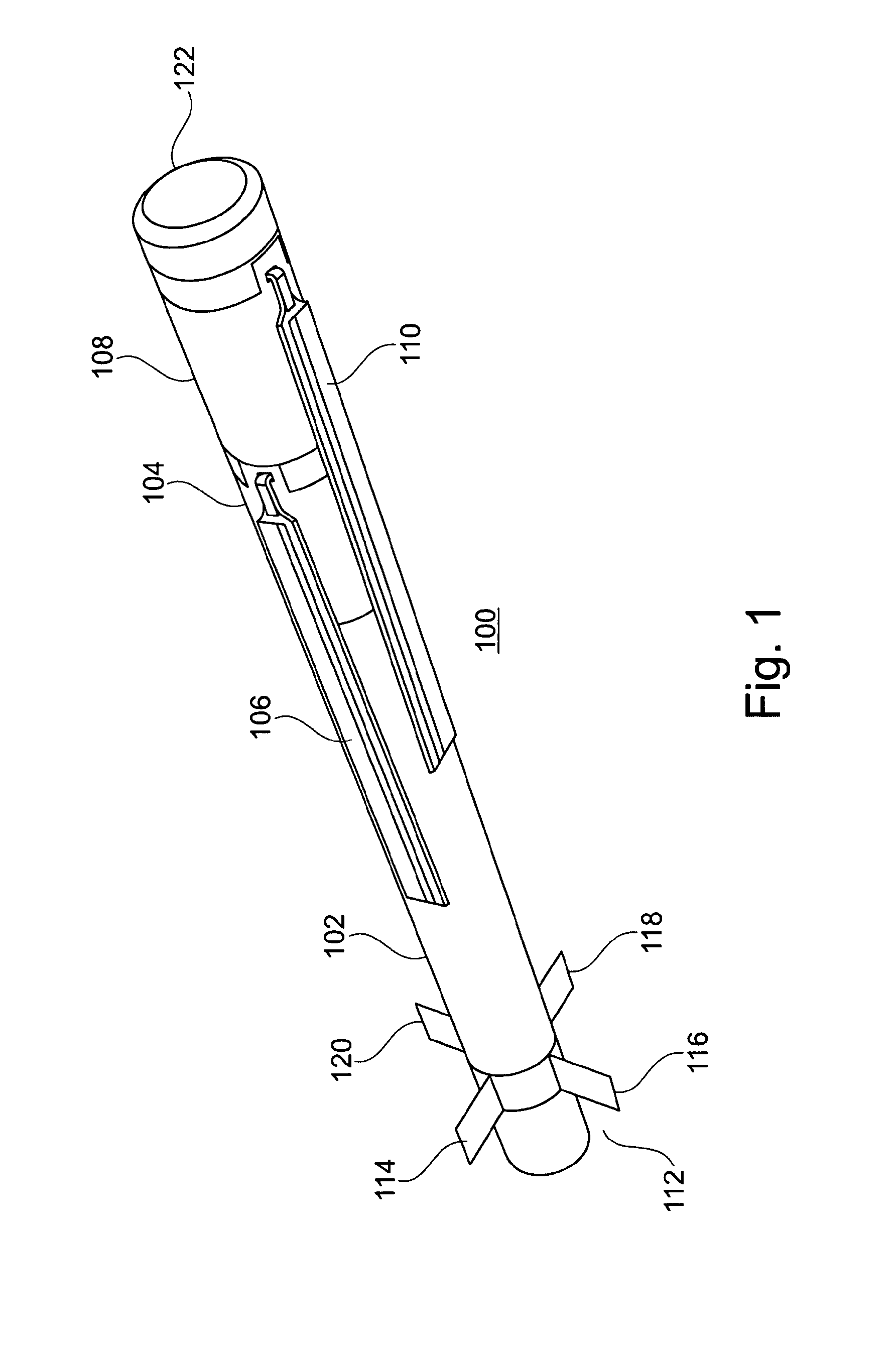
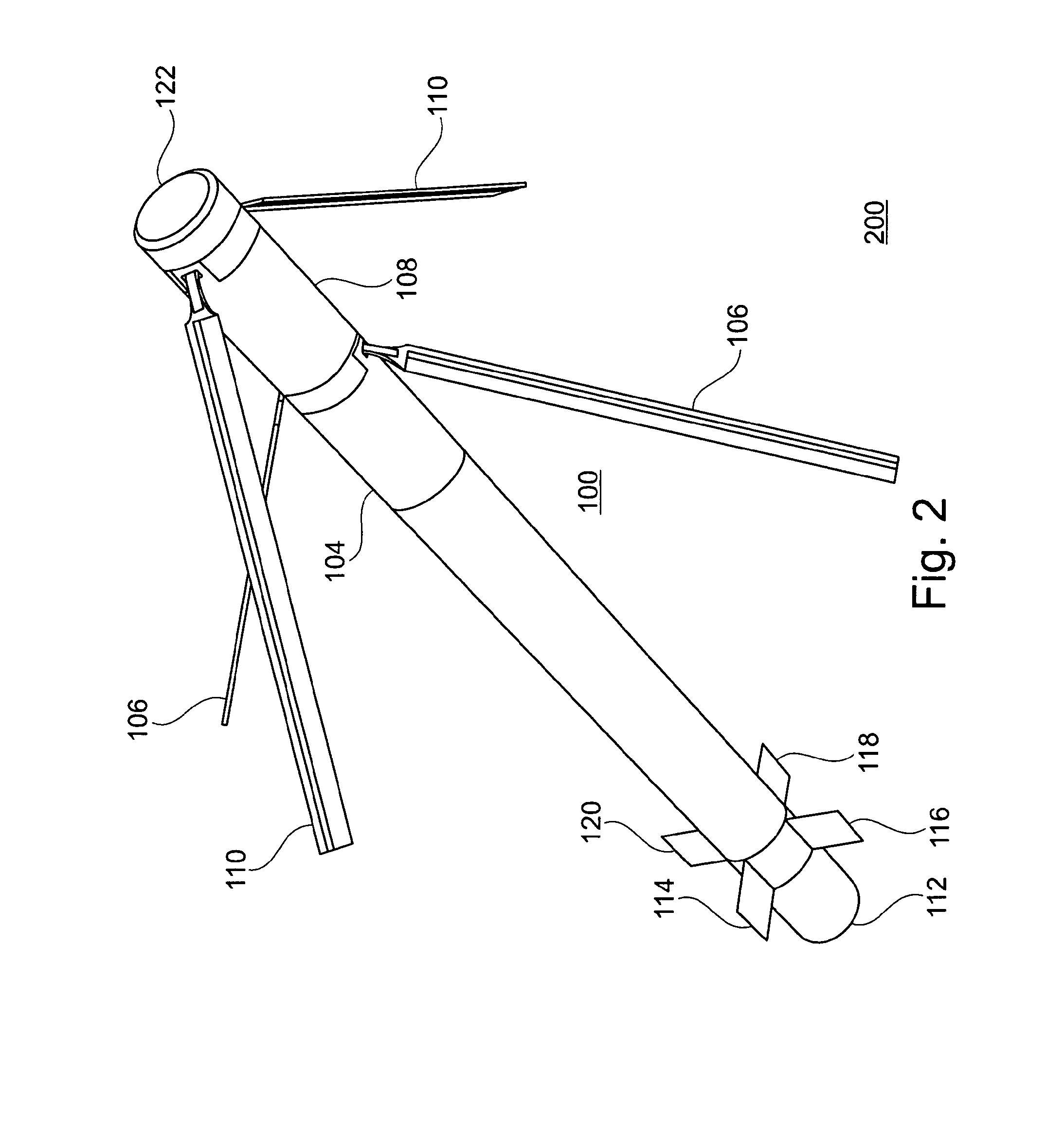
[0062]Referring to FIG. 1, there is shown a first perspective view of a rotary wing vehicle 100 comprising an elongate body 102, a first rotor system 104 bearing respective rotors of which only one rotor blade 106 is shown, a second rotor system 108 bearing respective rotors of which only one rotor blade 110 is shown. In all embodiments described herein, the rotor systems are arranged such that the rotors are counter-rotating, that is, the first rotor system is arranged to rotate its respective rotors in the opposite direction to the rotors of the second rotor system. The vehicle 100 also has a detachable launch or propulsion section 112, preferably, having respective fins 114 to 120. The vehicle has a nose cone 122. Preferred embodiments of the elongate body are substantially cylindrical with a substantially uniform circular cross section. The rotor blades 106 and 110 are shown in the stowed or launch position, in which they are substantially parallel with the longitudinal axis of ...


PUM


Abstract

Embodiments of the present invention relate to a rocket or ballistic launch rotary wing air vehicle.

Description

FIELD OF THE INVENTION[0001]Embodiments of the present invention relate to an air vehicle and, more particularly, to a rotary wing vehicle.BACKGROUND TO THE INVENTION[0002]Increasingly the military, law enforcement agencies and civilian operators use unmanned air vehicles (UAVs) for reconnaissance, surveillance, search and enhanced situational awareness. Typically, a UAV is tasked by a ground control system that is operated by an operator. Data are exchanged between the UAV and the ground control system during any given mission using telemetry.[0003]Wider adoption of UAVs for such tasks depends upon many factors. Those factors include, for example, ease and speed of deployment, the number of operators required to fly the UAV, the weight of the Unmanned Air System (UAS) of which the UAV is a part, including the ground control station and / or associated power supplies and payloads, the size of the vehicle, whether or not further equipment is required to launch the vehicle and the compl...

Claims


Application Information

Patent Timeline
Patent Type & Authority Applications(United States)
IPC IPC(8): B64C27/605B64C27/50B64D27/02B64C27/08B64C27/59B64D27/24B64C27/00B64F1/04
CPCB64C27/32B64F1/04B64C27/605B64C39/024B64C2201/027B64C2201/042B64C2201/102B64C2201/108B64D27/24B64D27/02B64C27/59B64C27/50B64C27/08B64C27/00B64C27/58B64U30/12B64U10/13B64U30/20B64U50/19B64C27/10B64C37/00
Inventor GREEN, JOHNGEOGHEGAN, PHILIPSNOOK, MICHAEL ALEXANDER
Owner BLUE BEAR SYST RES
Why Eureka
Try Eureka