Colour lighting control method for improving image quality in a vision system

a technology of vision system and control method, which is applied in the direction of television system, instrument, color signal processing circuit, etc., can solve the problems of inconvenient operation, increased inspection equipment cost, and complex methods, and achieve clear and rapid derived results, improve image quality, and maximize image quality

Active Publication Date: 2014-10-09
KOREA INST OF IND TECH
View PDF10 Cites 6 Cited by
  • Summary
  • Abstract
  • Description
  • Claims
  • Application Information

AI Technical Summary

Benefits of technology

[0025]According to the color lighting control method for improving image quality of a vision system of the present invention, an image histogram that is a distribution graph for displaying the number of pixels corresponding to each monochrome level intensity is calculated through image data obtained from a camera, and color lighting conditions that maximize a standard deviation or maximum value of the image histogram are detected, and thus, optimal color lighting conditions for obtaining a high-quality image may be clearly and rapidly derived.
[0026]That is, when the optimal color lighting conditions are derived, a criterion on an image having optimal quality is clearly digitized as a state where the standard deviation or maximum value of the image histogram is largest, so as to clearly and rapidly derive the optimal color lighting conditions, thereby maximizing the quality of the image obtained from the camera.
[0027]Furthermore, in the case where the optimal color lighting conditions are derived according to whether an image has a largest maximum value of the image histogram, the maximum value is calculated within bottom 85-95% of the entire range of monochrome level intensity excluding top 5-15% thereof, thereby preventing an error on determination of the optimal color lighting conditions due to a hot pixel of the camera or pixel saturation caused by a highly-reflective metal part of an inspection subject.
[0028]Similarly, the maximum value is calculated within top 85-95% of the entire range of monochrome level intensity excluding bottom 5-15% thereof, thereby preventing an error on determination of the optimal color lighting conditions due to a dark area of an image which occurs when an image-shooting area of the camera is larger than an irradiation area of color lighting.
[0029]Furthermore, a steepest decent method or golden section search method is used to detect the color lighting conditions that maximize the standard deviation or maximum value of the image histogram. Therefore, the number of times of shooting images by the camera is remarkably reduced, and thus, operations required for detecting the optimal color lighting conditions may be reduced and a life of a camera detector may be prevented from being shortened.

Problems solved by technology

However, this method is not only complex but also subjective since whether found lighting conditions are optimal is determined depending on eyesight of the operator.
Moreover, whenever inspection subjects are changed, such a complex setting operation should be performed again, causing inconvenience to the operator.
When various types of inspection subjects are inspected, an additional vision system may be provided for each inspection subject in order to resolve the above-mentioned inconvenience, but this method increases the cost of inspection equipment.
Therefore, in the field of a vision system to which color lighting is applied, it is an important issue to develop an optimal color lighting control method for maximizing the quality of an image shot by a monochrome camera of a vision system so that a processing system rapidly and correctly determines the quality of an inspection subject by reading the image.
However, this conventional color lighting control method merely achieves improvement with respect to automatic acquisition and analysis of an image, but requires a large amount of images to be acquired and analyzed.
Therefore, it takes a long time to find optimal color lighting conditions, and the life of a detector of a camera is shortened due to shooting of a large amount of images.
Therefore, it may be difficult to determine an optimal image if two images which have different color lighting conditions have conflicting superiority with respect to contrast.
However, in this case, since the optimal image is not determined in consideration of all inspection regions, the reliability of the determination is relatively low.
That is, according to the conventional color lighting control method, a criterion for determining an optimal image is ambiguous, and thus, the method is not reliable even though optimal color lighting conditions may be found.

Method used


Image

  • Colour lighting control method for improving image quality in a vision system
  • Colour lighting control method for improving image quality in a vision system
  • Colour lighting control method for improving image quality in a vision system

Examples


Embodiment Construction

[0036]Hereinafter, embodiments of the present invention will be described in detail with reference to the accompanying drawings so that the present invention is easily carried out by a person of ordinary skill in the technical field to which the present invention belongs (hereinafter, referred to as “a person skilled in the art”). However, the present invention may be implemented in various different forms and should not be construed as being limited to the embodiments described herein.

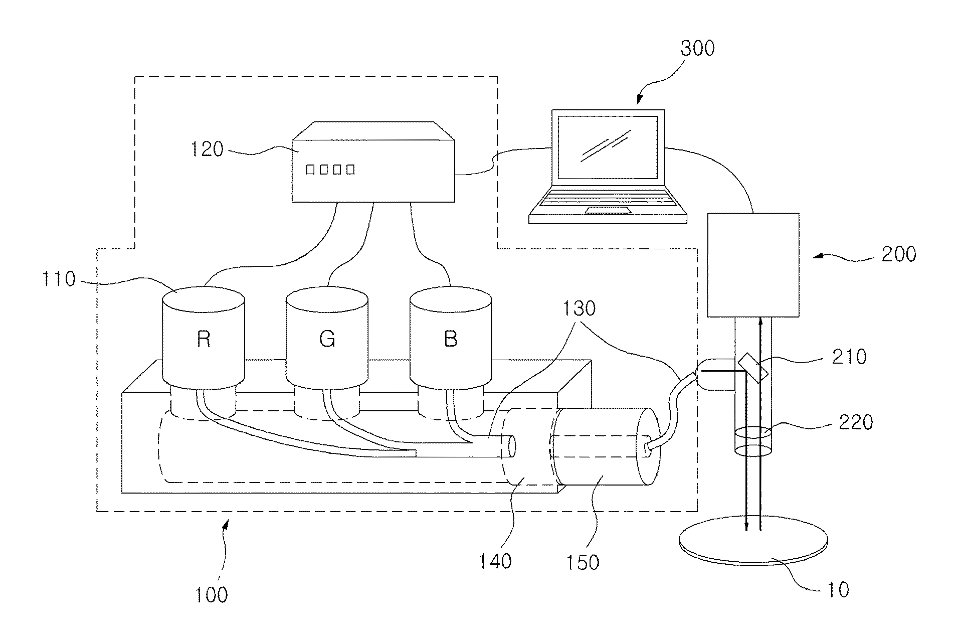
[0037]A color lighting control method for improving image quality of a vision system (hereinafter, referred to as a “color lighting control method”) according to the present invention is applied to a vision system, which has a function of shooting and collecting digital images of inspection subjects such as a wafer and a semiconductor chip and is provided to inspection equipment developed to automatically, rapidly and correctly perform various visual inspections on outward appearances of the inspectio...


PUM


Abstract

Provided is a color lighting control method including a lighting device having a plurality of lighting unit, the method including the steps of: (a) applying predetermined input voltages to the plurality of lighting units respectively and obtaining image data through the camera; (b) calculating an image histogram that is a distribution graph for displaying the number of pixels corresponding to each monochrome level intensity through the image data; (c) calculating a standard deviation of the image histogram; and (d) calculating an optimal input voltage value for each of the plurality of lighting units within an adjustment range of the predetermined input voltages, wherein the optimal input voltage value maximizes the standard deviation.

Description

TECHNICAL FIELD[0001]The present invention relates to a color lighting control method for improving image quality of a vision system, and more particularly, to a color lighting control method in which color light is irradiated to an inspection subject to maximize the quality of an image shot by a camera and optimal color lighting conditions for obtaining such a high-quality image are rapidly and correctly set, thereby enabling a processing system to rapidly and correctly determine the quality of the inspection subject by reading an image collected by a vision system provided with a monochrome camera.BACKGROUND ART[0002]In general, a vision system is provided to inspection equipment developed to automatically, rapidly and correctly perform various visual inspections on an outward appearance of an inspection subject, which have depended on human eyesight, so as to shoot and collect digital images of the inspection subject and transfer the collected images to a processing system having...

Claims


Application Information

Patent Timeline
Patent Type & Authority Applications(United States)
IPC IPC(8): H04N9/07
CPCH04N5/2354H04N9/07G01N21/9501G01N21/8806H04N23/74H04N23/12
Inventor KIM, HYUNG TAEKIM, SEUNG TAEK
Owner KOREA INST OF IND TECH
Why Eureka
Try Eureka