

Controllable waveguide for near-eye display applications
- Summary
- Abstract
- Description
- Claims
- Application Information
AI Technical Summary
Benefits of technology
Problems solved by technology
Method used
Image

Examples
Embodiment Construction
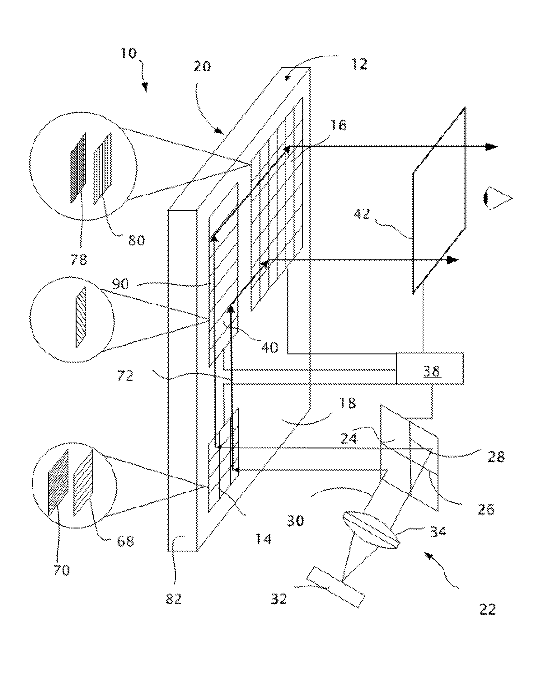
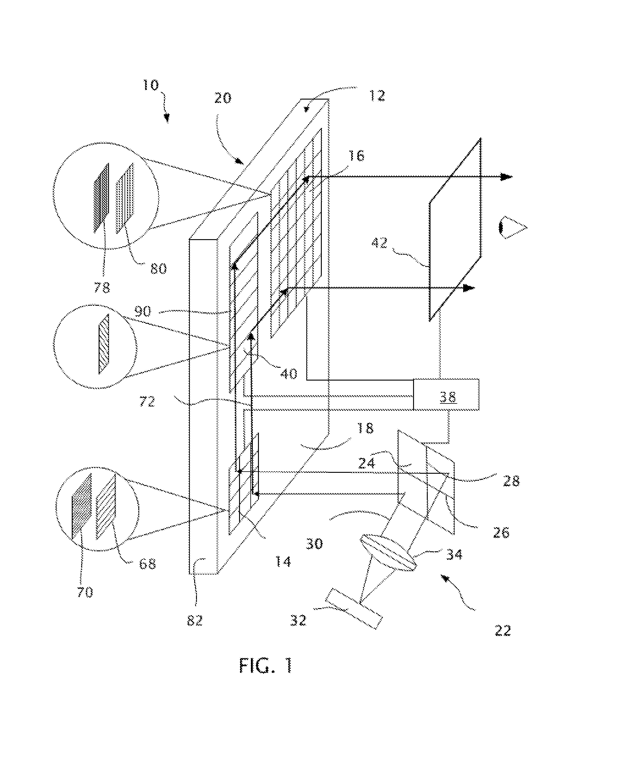
[0026]With reference to FIG. 1, a near-eye display 10 includes a plate-shaped waveguide 12 having a controllable input aperture 14, a controllable output aperture 16 and a controllable intermediate diffractive optic 90. The plate-shaped waveguide 12 is preferably a transmissive plate having a back surface 18 (facing the viewer's eye) and a front surface 20 (facing the ambient environment), with both the back and front surfaces 18 and 20 being exposed to air or another medium with a refractive index that is preferably close to the refractive index of air.
[0027]The plate-shaped waveguide 12 can be made of various transmissive optical materials, such as BK7 glass having a nominal refractive index of 1.527, and has dimensions for transmitting light to a position within the field of view of a viewer from an off-axis position at which the light can be injected. For example, the plate-shaped waveguide 12 can have a length of approximately 60 millimeters for reaching the eye position, a hei...
PUM
 Abstract
Description
Claims
Application Information