Portable intermittent pneumatic compression system

a pneumatic compression and intermittent technology, applied in the field of intermittent pneumatic compression systems, can solve the problems of inconvenient use and management, device typically lack true portability, tripping hazards, etc., and achieve the effect of reducing fall risks and improving patient discomfor

Active Publication Date: 2014-10-09
INNOVAMED HEALTH
View PDF39 Cites 37 Cited by
  • Summary
  • Abstract
  • Description
  • Claims
  • Application Information

AI Technical Summary

Benefits of technology

[0006]To solve one or more of the problems set forth above, in an exemplary implementation of the invention, an intermittent pneumatic compression system that provides exhaust between the wrap and patient's leg, avoids tubes and is operable on a conventional battery is provided. The system allows true portability while improving patient discomfort, reducing fall risks, and providing the desired therapeutic and prophylactic compression.

Problems solved by technology

Typically, such devices require tubing, which present a tripping hazard and are inconvenient to use and manage.
Additionally, such devices typically lack true portability.
Conventional pumping systems are usually dependent upon an AC power source and too bulky to provide a patient meaningful opportunity to travel while using the system.
Furthermore, conventional devices cause discomfort to a patient by preventing or severely limiting circulation to the patient's wrapped limb.
As a result, patients often complain of sweat, soreness and general discomfort of the limb.
Moreover, conventional systems obtain pressure readings at the inlet port, which does not necessarily provide an accurate measure of pressure at the most remote parts of a bladder.
Thus, the requisite pressures may not be achieved at such remote parts of the bladder during pumping.

Method used


Image

  • Portable intermittent pneumatic compression system
  • Portable intermittent pneumatic compression system
  • Portable intermittent pneumatic compression system

Examples


Embodiment Construction

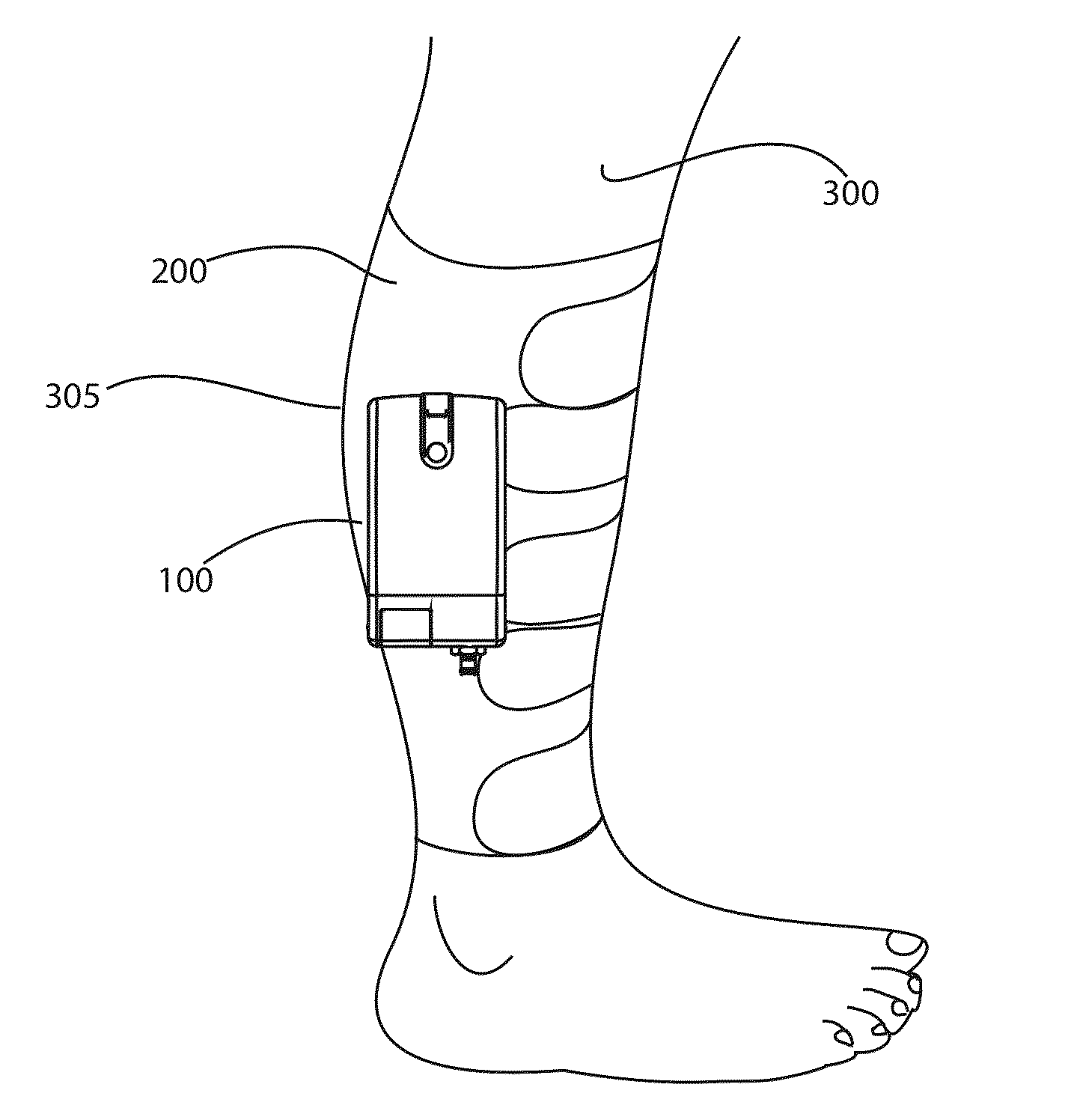
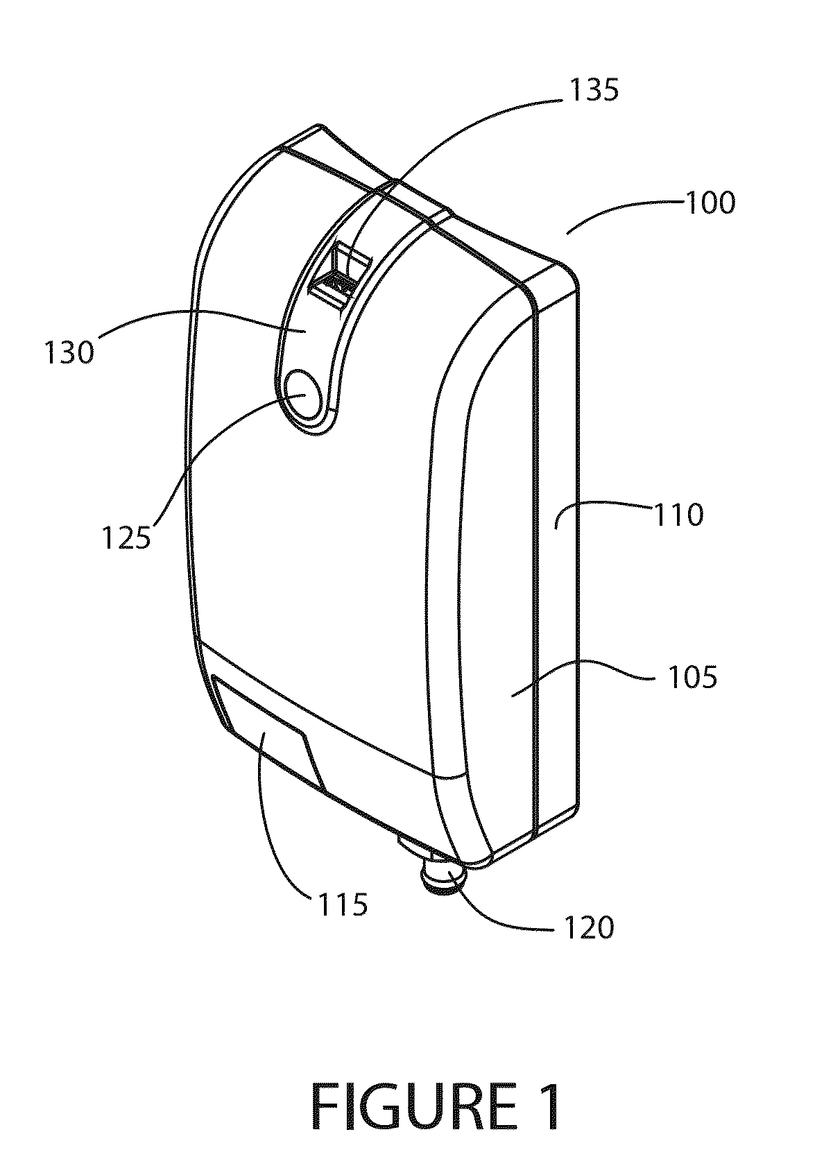
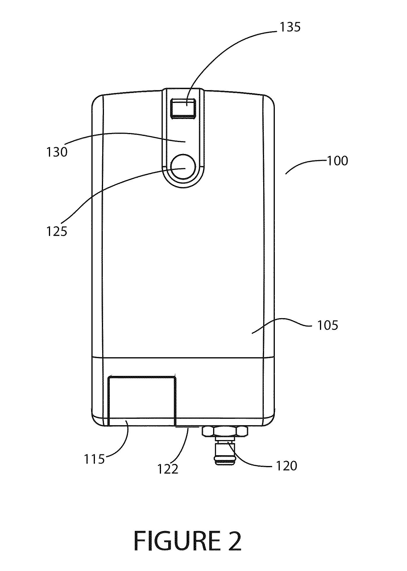
[0035]Referring to FIG. 1, a top perspective view of an exemplary controller module 100 for a portable intermittent pneumatic compression system according to principles of the invention is shown. The module includes a front cover 105, a back cover 110 which is curved to accommodate the shape of a limb, an auxiliary fill port 120, a battery cover 115 leading to a battery compartment, transparent or translucent windows 125, 130 for visibility of status lights contained in the module 100.

[0036]The auxiliary fill port 120 is an optional feature which, in one embodiment, includes a fitting for coupling the module 100 to wraps with fillable bladders other than the wrap as described herein. When the module 100 is used with the wrap described herein, the auxiliary fill port 120 is not used.

[0037]In an alternative embodiment, the auxiliary fill port 120 is a removable adapter that may be connected to a fill port of a wrap in accordance with principles of the invention. By connecting one or m...


PUM


Abstract

An intermittent pneumatic compression system provides exhaust between a wrap and patient's leg, avoids tubes and is operable on a conventional battery. The system allows true portability while improving patient discomfort, reducing fall risks, and providing desired therapeutic and prophylactic compression.

Description

RELATED APPLICATION[0001]This application is a nonprovisional and claims the benefit of priority of U.S. provisional application No. 61 / 794,235 filed Mar. 15, 2013, the entire contents of which are incorporated herein.FIELD OF THE INVENTION[0002]This invention relates to intermittent pneumatic compression systems, and, more particularly, to a portable intermittent pneumatic compression system that provides exhaust between the wrap and patient's leg and avoids tubes.BACKGROUND[0003]A major concern for immobile patients and like persons are medical conditions that form clots in the blood, such as, deep vein thrombosis (DVT) and peripheral edema. These conditions associated with patient immobility may be controlled or alleviated by applying intermittent pressure to a patient's limb, such as, for example, a leg to assist in blood circulation. Such compression devices are typically constructed of two sheets of material secured together at the seams to define one or more fluid impervious ...

Claims


Application Information

Patent Timeline
Patent Type & Authority Applications(United States)
IPC IPC(8): A61H9/00
CPCA61H9/005A61H9/0092A61H2201/164A61H2201/165A61H2201/5002A61H2201/5071A61H2205/106A61H2209/00A61H2201/0103
Inventor ZEUTZIUS, TURNER LUCASWILLIAMS, WADE R.ZEUTZIUS, JOSEPH
Owner INNOVAMED HEALTH
Why Eureka
Try Eureka