
Handle for a medical instrument

a technology for medical instruments and handles, applied in the field of handles for medical instruments, can solve problems such as not being able to achieve the best solution, and achieve the effect of improving operating ability

Active Publication Date: 2014-10-09
RICHARD WOLF GMBH
View PDF6 Cites 0 Cited by
  • Summary
  • Abstract
  • Description
  • Claims
  • Application Information

AI Technical Summary

Benefits of technology

The invention aims to improve the handle of a medical instrument by adding a pivotable actuation lever that is connected to the instrument's actuation element. This lever is designed to be easily operated with one hand, making it easier to move the instrument's parts into different positions. The lever is connected to the actuation element in a way that allows for smooth movement in two directions. This design also ensures that the force used to move the instrument is minimized, making it easier for the user to operate. The actuation lever is conveniently located near the grip on the instrument, making it easy to use with one hand. Overall, the invention simplifies the use of the instrument and reduces the effort required to move its parts into different positions.

Problems solved by technology

The handle of the instrument known from DE 10 2009 051 515 A1 represents a significant improvement compared to handles with whose actuation elements only one function can be carried out in each case, wherein this handle however still does not represent the best possible solution from an ergonomic point of view.

Method used


Image

  • Handle for a medical instrument
  • Handle for a medical instrument
  • Handle for a medical instrument

Examples


Embodiment Construction

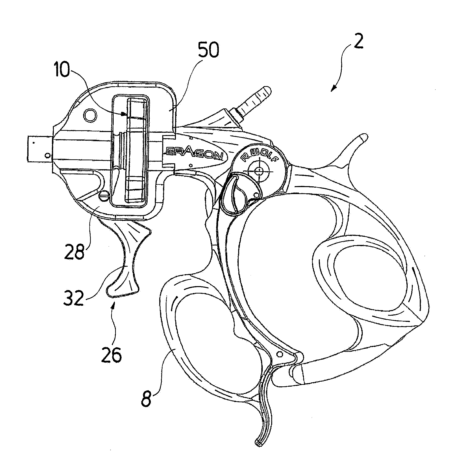
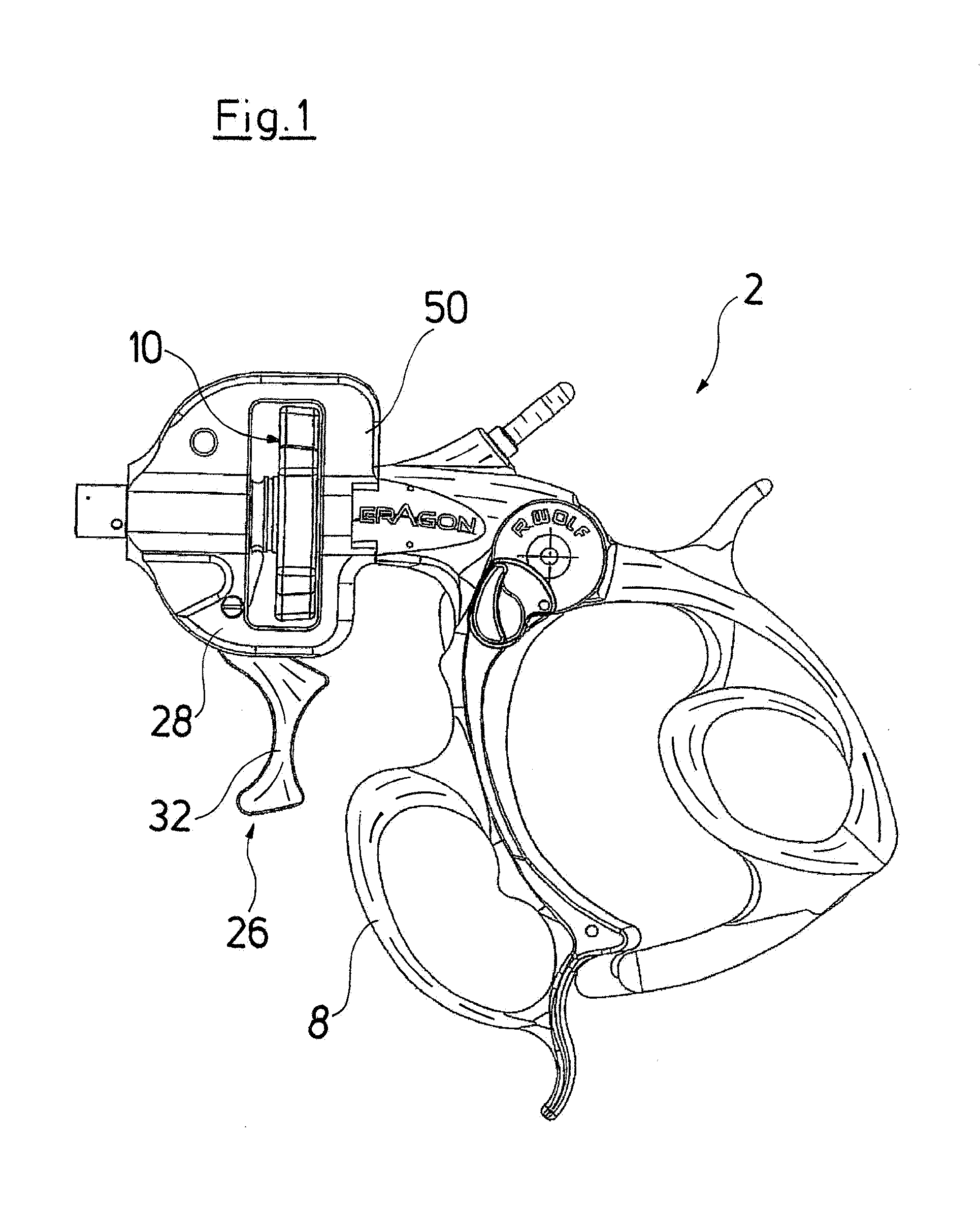
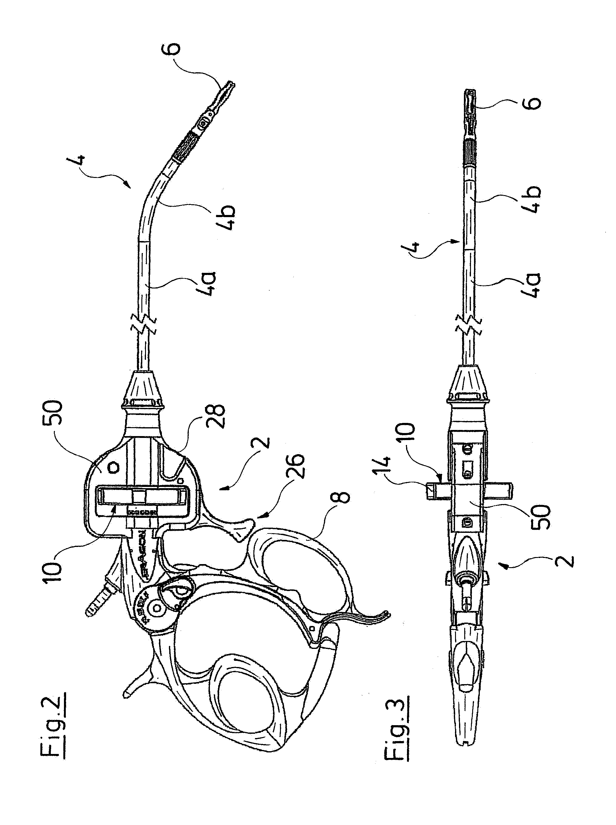
[0031]The handle 2 represented in FIG. 1 is part of an endoscopic hollow shank instrument, as is represented in FIGS. 2 and 3. With this hollow shank instrument, a rigid hollow shank 4 is arranged distally of the handle 2 and comprises a straight, aligned hollow shank section 4a and a bent, distal shank section 4b which connects thereto obliquely to the shank section 4a. A tool 6 in the form of a gripping forceps is arranged at the distal end of the hollow shank 4. The hollow shank 4 is rotatably mounted on the handle 2 about the longitudinal axis of the proximal shank section 4a, and thus is rotatable relative to the handle 2. The tool 6 in turn is rotatable relative to the hollow shank 4.

[0032]The handle 2 comprises an actuation element 10 for the rotation of the hollow shank 4 and the tool 6, and this element extends between a grip part 8, which is fixedly arranged on the handle 2 and which extends essentially normally to a main axis A (FIG. 4) of the handle 2, and the distal end...


PUM


Abstract

A handle for a medical instrument includes an actuation element, which is arranged on the handle and which is displaceable into at least a first and a second functional position. The actuation element can be moved in a plane transverse to its displacement direction, in each of the first and second functional positions, for carrying out a function. A pivotable actuation lever is arranged in the handle, the actuation lever being coupled in movement to the actuation element for displacing the actuation element into the at least two functional positions.

Description

CROSS-REFERENCE TO RELATED APPLICATIONS[0001]This application is a Section 371 of International Application No. PCT / EP2012 / 071462, filed Oct. 30, 2012, which was published in the German language on May 10, 2013, under International Publication No. WO 2013 / 064487 A1 and the disclosure of which is incorporated herein by reference.BACKGROUND OF THE INVENTION[0002]The invention relates to a handle for a medical instrument.[0003]A handle of a medical instrument is usually to be understood as the part of the instrument by which the instrument is manually held and led by a grip part arranged there and on which one or more actuation elements are arranged for carrying out the functions which can be executed with the instrument.[0004]Apart from handles, with whose actuation elements respectively only one function of a medical instrument can be carried out, a medical instrument having a handle is known from German published patent application DE 10 2009 051 515 A1 (counterpart: US patent appli...

Claims


Application Information

Patent Timeline
IPC IPC(8): A61B17/00A61B90/00
CPCA61B17/2909A61B2017/2923A61B17/00234A61B2017/292A61B2017/2929A61B2017/0046A61B2017/00389A61B2017/00393
Inventor PRESTEL, STEPHANFALK, ERNSTKORNER, EBERHARDBOEBEL, MANFRED
Owner RICHARD WOLF GMBH
Learn More