Capacity control valve

a technology of capacity control and valve body, which is applied in the direction of valve body, positive displacement liquid engine, machine/engine, etc., can solve the problems of axial bending of the rod, large longitudinal length of the body, and long structure, and achieve the effects of improving the sliding friction of the operating rod, improving anti-abrasion, and anti-sticking

Active Publication Date: 2005-02-17
EAGLE INDS
View PDF11 Cites 23 Cited by
  • Summary
  • Abstract
  • Description
  • Claims
  • Application Information

AI Technical Summary

Benefits of technology

[0017] According to a capacity control valve of the present invention, the operating rod is processed at no more than 500° C. by a low temperature surface hardening treatment. The low temperature surface hardening treatment applied to the surface of the operating rod in which a surface thickness of less than 10×10−6 m is processed at no more than 500° C. can provide an improved anti-abrasion, anti-sticking and a low surface roughness of the operating rod. More particularly, a sliding friction of the operating rod improves since the operating rod is free from strains caused by the heat treatment. Roundness of the operating rod after the surface hardening treatment is approximately less than 0.5×10⁻⁶ m, thus a leakage of control fluid in the closing action of the valve body from a gap between the fit surfaces of the operating rod is effectively prevented. Further, anti-abrasion ability of the operating rod will improve. Machining cost of the operating rod is also decreased. Overall shape of the operating rod after the heat treatment exhibits little deformation caused by the heat treatment, and field experiments of the operating rod do not reveal any potential problem.

Problems solved by technology

In a capacity control valve of this kind, an operating rod mounting a valve body thereon is connected with a solenoid portion or a pressure sensitive device, thus the rod results in a long structure.
The operating rod 101, however, has a body of large longitudinal length and the heat treatment often causes an axial bending of the rod.
In addition, a small diameter of the operating rod 101 imposes difficulty on the use of grinding process.
In particular, a great difficulty resides in the grinding process of the valve face to arrange the valve face perpendicular to the rod axis.
The accumulated iron powder hampers the operation of the operating rod 101.
Such a heat treatment process, however, raises problems such as axial bending or strains.
In addition, a small radius of the operating rod makes it difficult to apply a grinding process thereto.
This grinding process is also demanding due to its necessity of machining in a perpendicular direction relative to the longitudinal axis, which increase a production cost.
Further, iron powders magnetized between the solenoid rod and the rod hole of the fixed iron core are attracted to the fixed iron core and makes the solenoid rod difficult to operate normally.
Such contaminants like the iron powders or the like are hard to be gotten rid of because they are introduced in a source fluid to begin with.
Also wear of the fixed iron core is tough to be avoided because of the limited availability of its material.
As a result, the abrasion powders attracted to the rod hole make the solenoid rod difficult to operate under a normal condition.

Method used


Image

  • Capacity control valve
  • Capacity control valve
  • Capacity control valve

Examples


Embodiment Construction

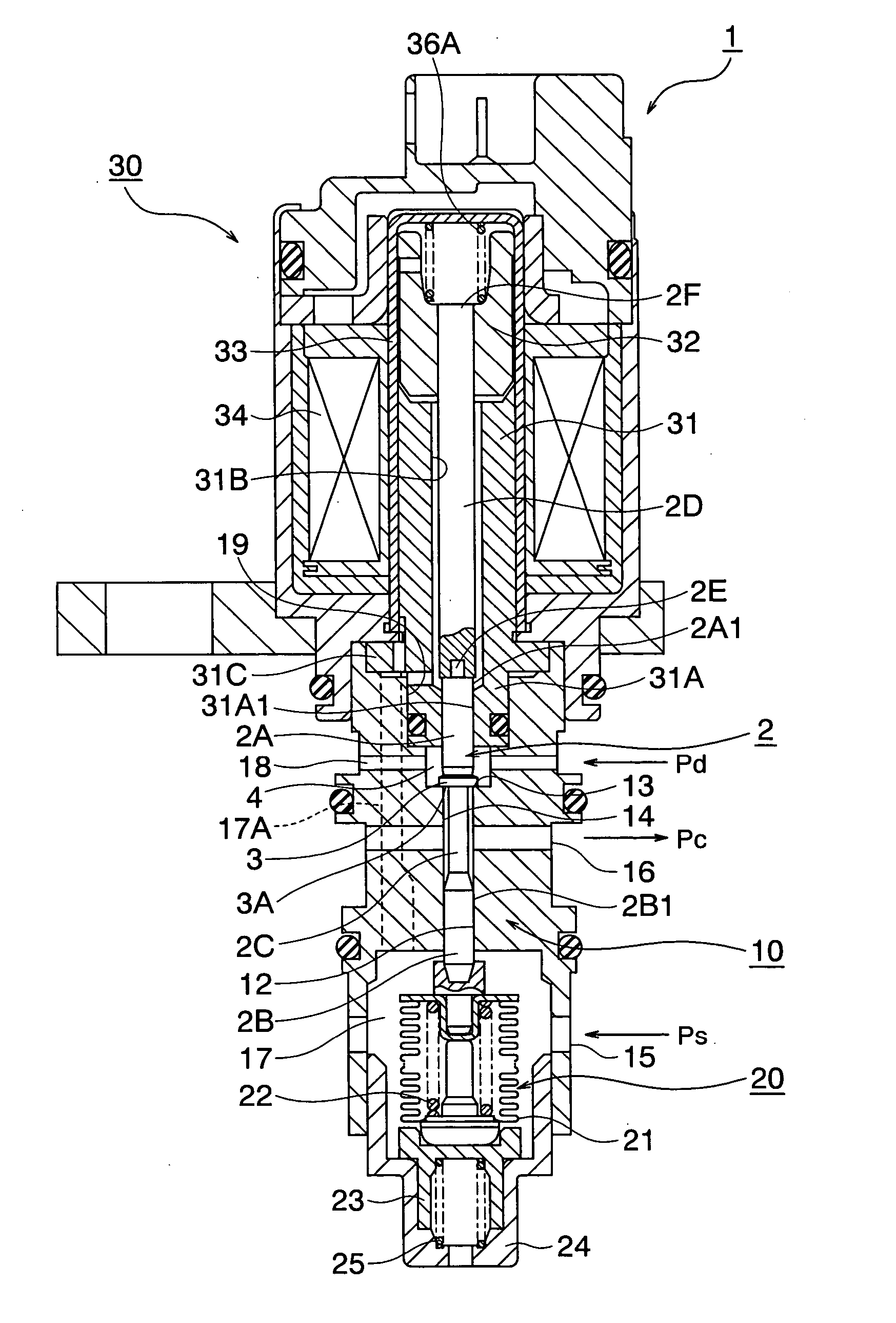
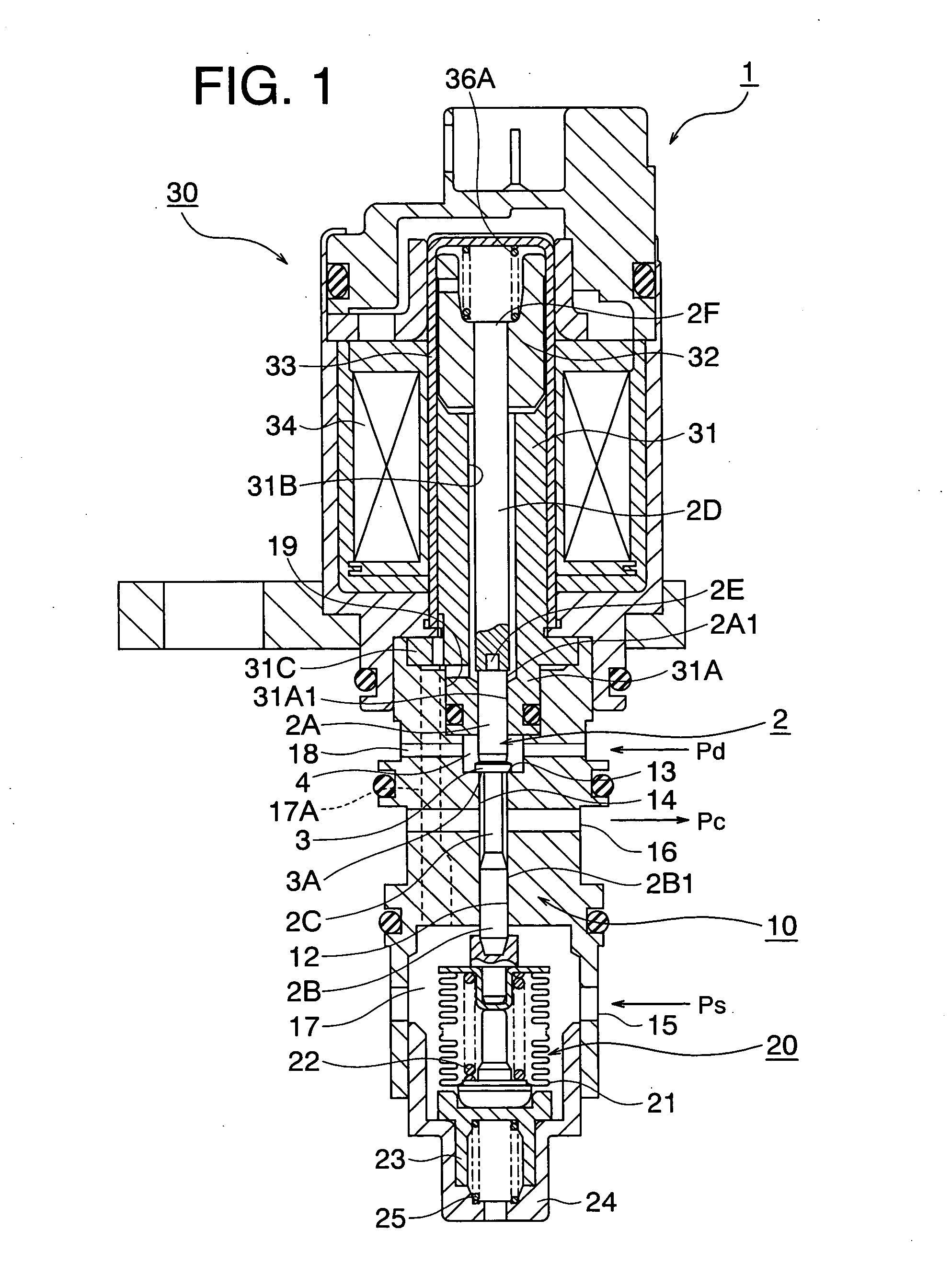
[0023] Described below is details of the figures of preferred embodiments of a capacity control valve constructed in accordance with the principles of the present invention. All the figures explained below are constructed according to actual design drawings with accurate dimensional relations.

[0024]FIG. 1 is a cross sectional view of a capacity control valve as a preferred embodiment relative to the present invention. In FIG. 1, a reference numeral 1 signifies a capacity control valve. The capacity control valve 1 disposes a valve housing 2 which forms an outer perimeter shape of the valve 1. The valve housing 10 disposes a through hole which defines respective portions of different diameters therein. The valve housing 10 is made of metal such as brass, aluminum or stainless, synthetic resin or the like.

[0025] The valve housing 10 retains an widely open end at one end of the through hole thereof. The open end is fitted with an end adjusting portion 24 which forms a pressure sensin...


PUM


Abstract

An object of the present invention is to improve an anti-abrasive property of an operating rod by using a surface hardening heat treatment without a post finishing process and to enhance a response of the operating rod by preventing powders from being attracted to a sliding surface of the operating rod. Another object is to decrease a machining cost of the operating rod. The capacitive control valve is comprised of a solenoid rod portion communicating with a moveable core of the solenoid portion, an operating rod connected with the solenoid rod portion, a valve body defined in the operating rod and opening or closing a control fluid passage hole and a fixed core oppositely arranged relative to the moveable core, the fixed core retaining a guide hole, the guide hole guiding the operating rod in freely moveable a manner which longitudinally extends through an internal bore wherein the operating rod is processed at no more than 500° C. by a low temperature surface hardening treatment.

Description

BACKGROUND OF THE INVENTION [0001] 1. Field of the Invention [0002] The present invention relates generally to a capacity control valve for variably modulating a capacity or a pressure of a process fluid in a control chamber through a valve body which is connected with an operating rod. More particularly, the invention relates to a capacity control valve in which anti-abrasion capability of the operating rod in an opening or closing action of the valve body is improved and its slide resistance is decreased where the valve body is integrally attached to the operating rod. [0003] 2. Description of the Related Art [0004] There have been known as a relative art 1 of the present invention capacity control valves for a variable displacement type swash plate compressor. In a capacity control valve of this kind, an operating rod mounting a valve body thereon is connected with a solenoid portion or a pressure sensitive device, thus the rod results in a long structure. The operating rod is al...

Claims


Application Information

Patent Timeline
Patent Type & Authority Applications(United States)
IPC IPC(8): F04B49/00F04B27/04F04B27/18F16K27/04F16K31/06
CPCF04B27/1804F04B2027/1827F04B2027/1854F04B2027/1859F16K27/048F05C2251/10F16K27/041F16K31/0624F16K31/0634F04B2027/1895Y10T137/7036
Inventor UEMURA, NORIOIWA, TOSHIAKISHIRAI, KATSUYASHIRAFUJI, KEIGOTAGUCHI, YUKIHIKO
Owner EAGLE INDS
Why Eureka
Try Eureka