
Position detection for lobe switching camshaft system

a camshaft and camshaft technology, applied in the direction of electrical control, process and machine control, instruments, etc., can solve the problems of engine torque and air-fuel ratio degrade, and achieve the effects of reducing valve lift, improving engine performance and efficiency, and shortening valve opening time duration

Active Publication Date: 2014-10-09
FORD GLOBAL TECH LLC
View PDF18 Cites 96 Cited by
  • Summary
  • Abstract
  • Description
  • Claims
  • Application Information

AI Technical Summary

Benefits of technology

The patent text describes a system that uses cam switching to adjust the timing of valves in engines. This allows the engine to perform better at different speeds and loads. The system also includes sensors to detect the position of the cam, allowing for adjustment of the torque actuators in the engine. The technical effects of this system include improved engine performance and efficiency by optimizing valve timing and adjusting the number of engine cylindrs that are actively operating based on driver demand.

Problems solved by technology

Consequently, if the engine control system adjusts the fuel amount in response to the expected activated cam profile, engine torque and air-fuel ratio may degrade.

Method used


Image

  • Position detection for lobe switching camshaft system
  • Position detection for lobe switching camshaft system
  • Position detection for lobe switching camshaft system

Examples


Embodiment Construction

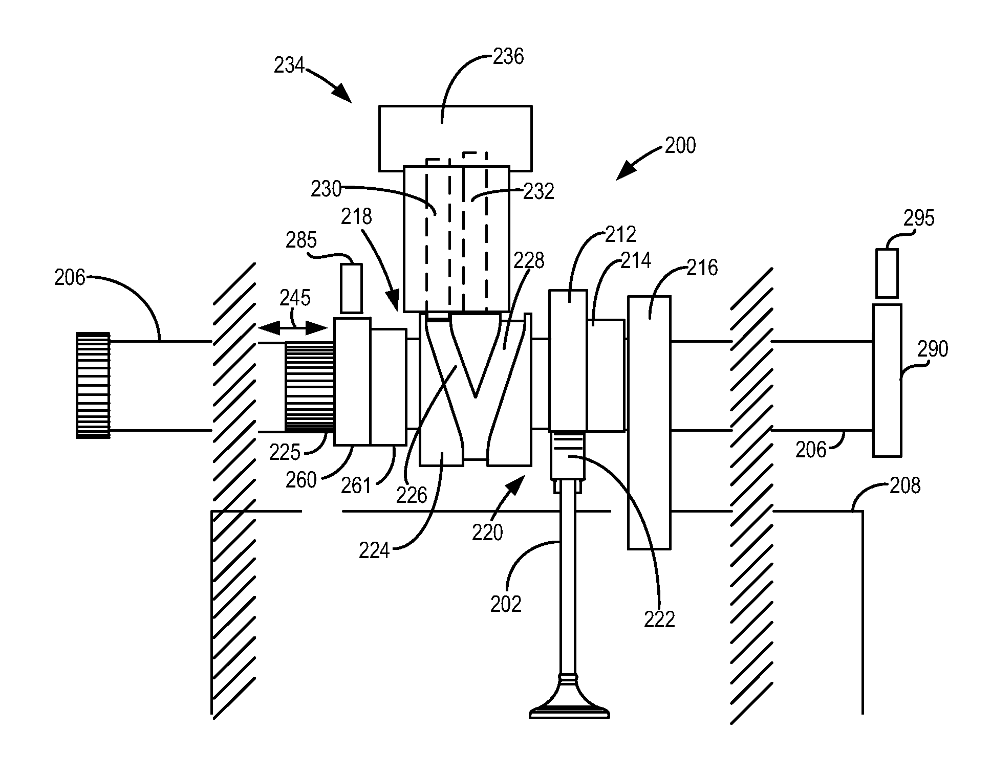
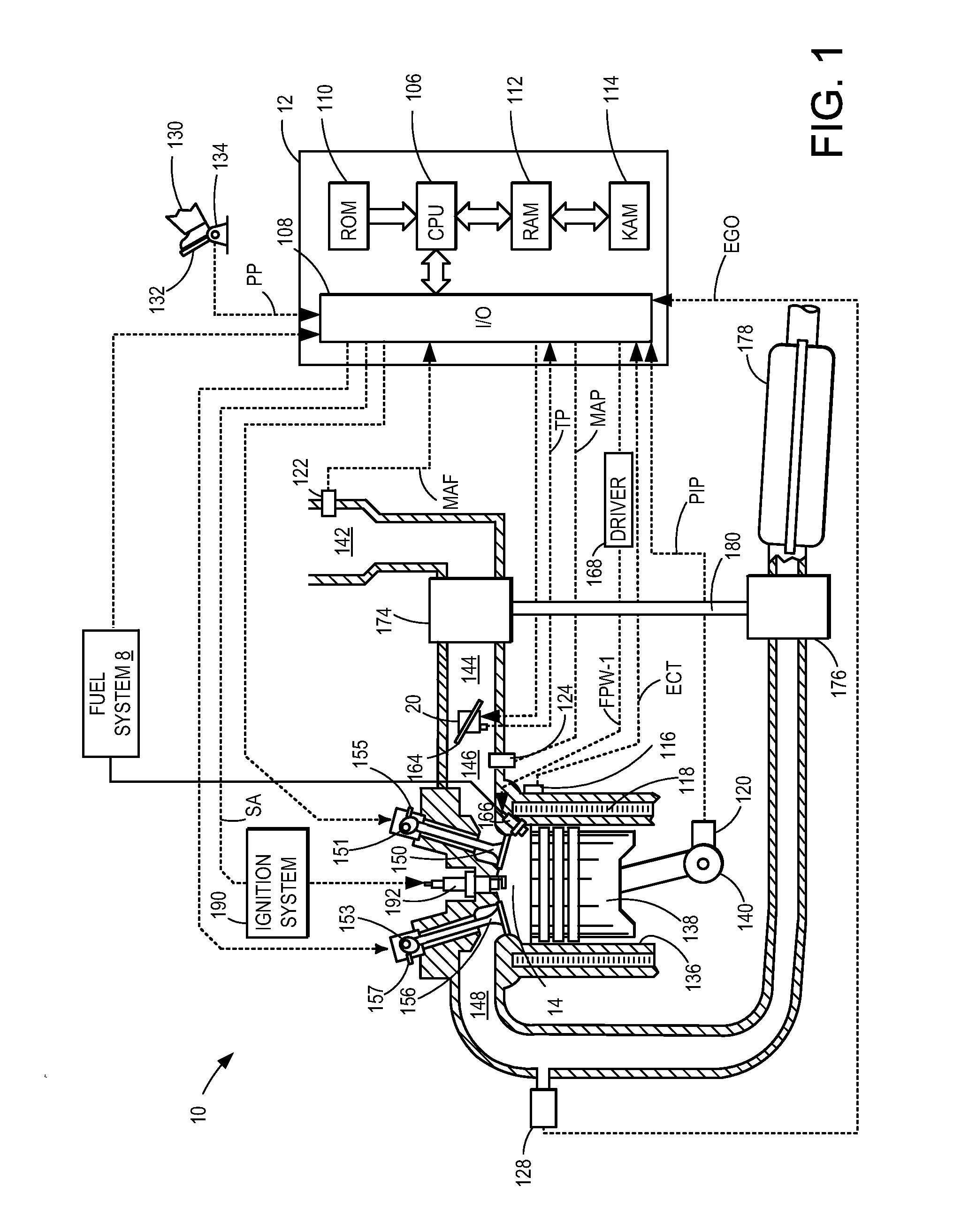
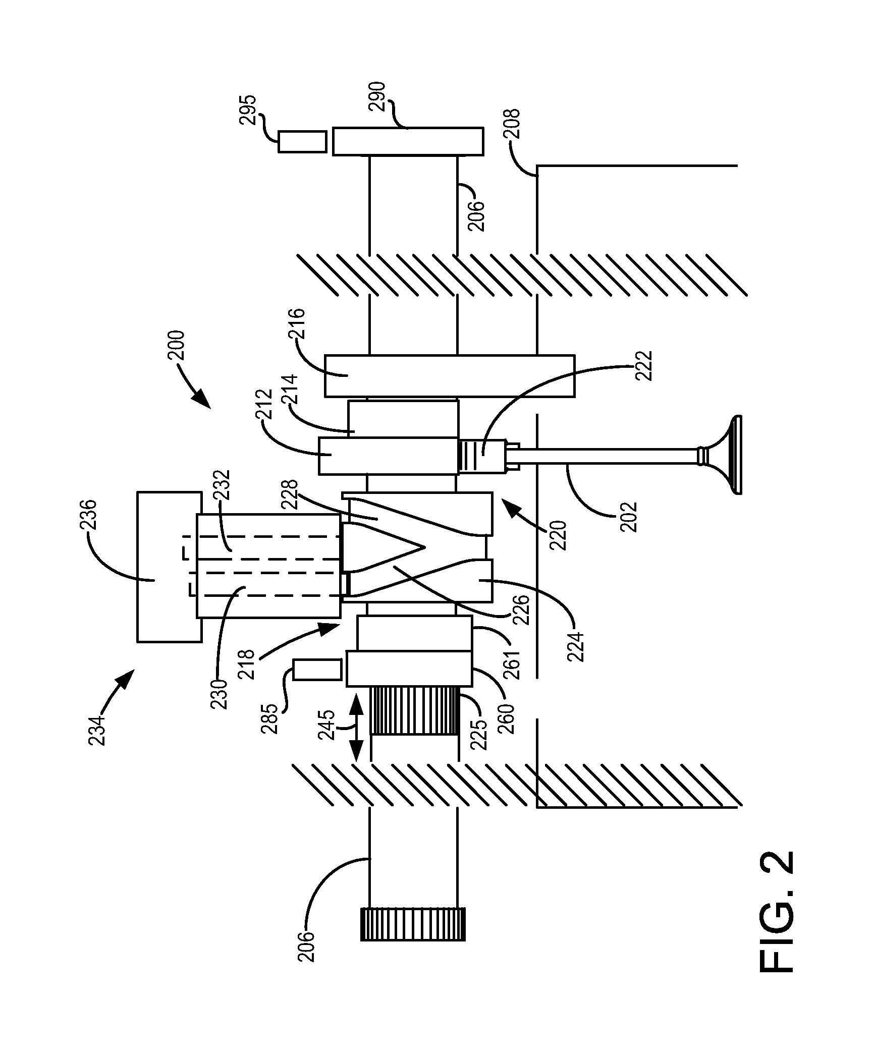
[0012]The following description relates to systems and methods for a cam switching system in an engine used to adjust valve lift of gas exchange valves in cylinders of the engine, such as the engine shown in FIG. 1. As shown in FIGS. 2 and 3, an engine may include a camshaft with multiple outer sleeves containing lobes splined to a central camshaft. By engaging a pin into a grooved hub in each sleeve, the axial position of the sleeve can be repositioned so that a different cam lobe engages a follower of a poppet valve of a cylinder, a slider finger follower, or a shaft-mounted follower. Activated cam profiles may be determined from sensor outputs as shown in FIGS. 4 and 5. FIGS. 5 and 6 show a plan view of a plurality of cam sleeves incorporated into a camshaft, the cam sleeves including different cam profiles for changing engine operation. A method for activating and confirming activation of various cam profiles is described in FIG. 7.

[0013]Turning now to the figures, FIG. 1 depict...


PUM


Abstract

Systems and methods for determining an active cam profile from a plurality of cam profiles is disclosed. The systems and methods may be used to determine how to operate an engine torque actuator or provide an indication of cam profile switching degradation.

Description

CROSS REFERENCE TO RELATED APPLICATION[0001]This application claims priority to U.S. Provisional Patent Application No. 61 / 808,873, filed Apr. 5, 2013, the entire contents of which are hereby incorporated herein by reference for all purposes.BACKGROUND AND SUMMARY[0002]Engines may use cam switching systems to adjust valve lift and valve opening duration of cylinder poppet valves. By adjusting valve lift and valve opening duration, it may be possible to tailor valve operation for engine operating conditions so that engine performance and efficiency may be improved. For example, reduced valve lift and shorter valve opening time durations may be applied at lower engine speeds and loads. On the other hand, higher valve lift and longer valve opening durations may be applied at higher engine speeds and loads. Additionally, cam switching systems may be used to deactivate selected engine cylinders during low driver demand conditions to increase efficiency of operating engine cylinders.[0003...

Claims


Application Information

Patent Timeline
IPC IPC(8): F02D35/02F02D41/30
CPCF02D41/3005F02D35/02F01L13/0036F01L2013/0052F02D19/10Y02T10/30F01L1/047F02P17/00F01L13/0042F01L2013/0078
Inventor GLUGLA, CHRIS PAULDOERING, JEFFREY ALLENUHRICH, MICHAEL JAMES
Owner FORD GLOBAL TECH LLC
Learn More