Information communication method

a technology of information communication and communication function, applied in the field of information communication method, can solve the problems of insufficient computational performance of home electric appliances to have a communication function, and insufficient communication function, and achieve the effect of low computational performan

Active Publication Date: 2014-10-16
PANASONIC INTELLECTUAL PROPERTY CORP OF AMERICA
View PDF1 Cites 83 Cited by
  • Summary
  • Abstract
  • Description
  • Claims
  • Application Information

AI Technical Summary

Benefits of technology

[0009]An information communication method disclosed herein enables communication between various devices including a device with low computational performance.

Problems solved by technology

However, there are home electric appliances whose computational performance is insufficient to have a communication function, and home electric appliances which do not have a communication function due to a matter of cost.

Method used


Image

  • Information communication method
  • Information communication method
  • Information communication method

Examples


embodiment 1

[0489]The following is a description of the flow of processing of communication performed using a camera of a smartphone by transmitting information using a blink pattern of an LED included in a device.

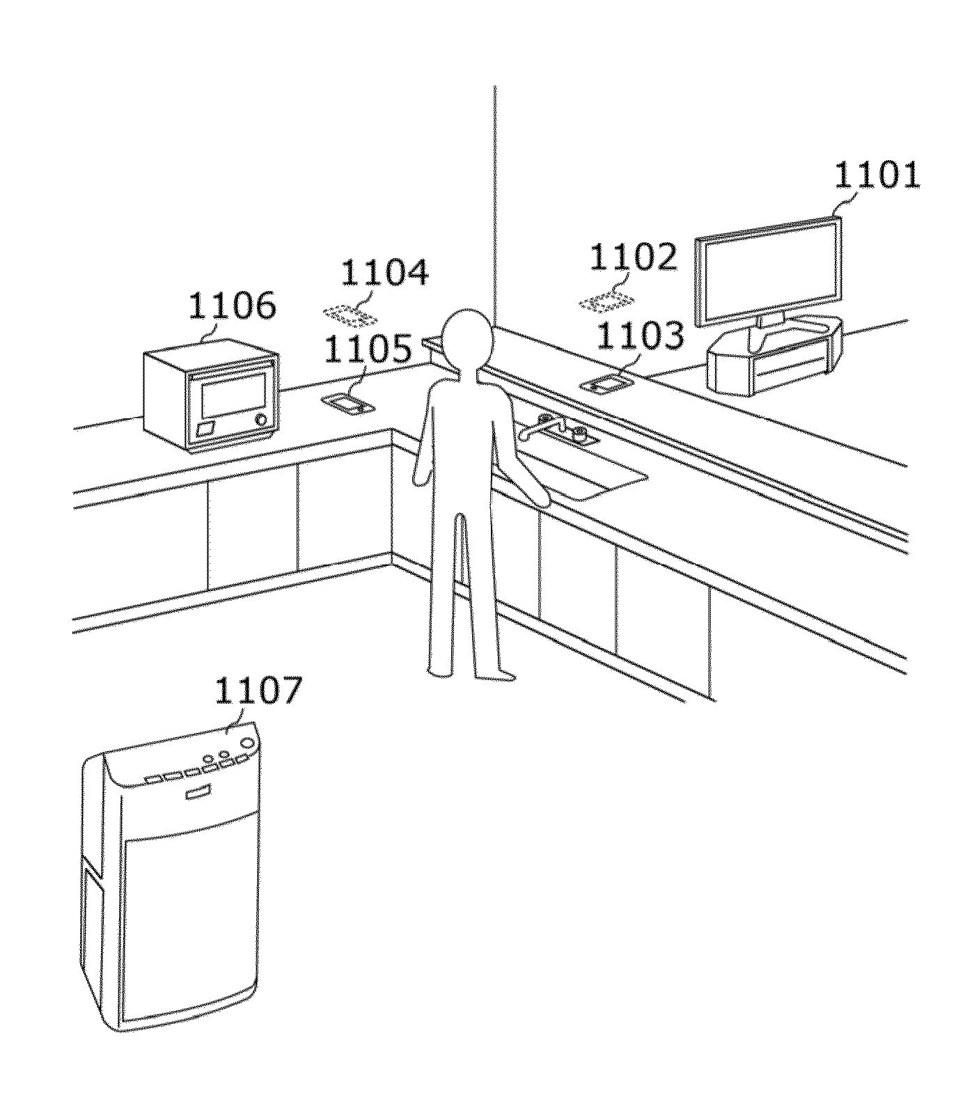
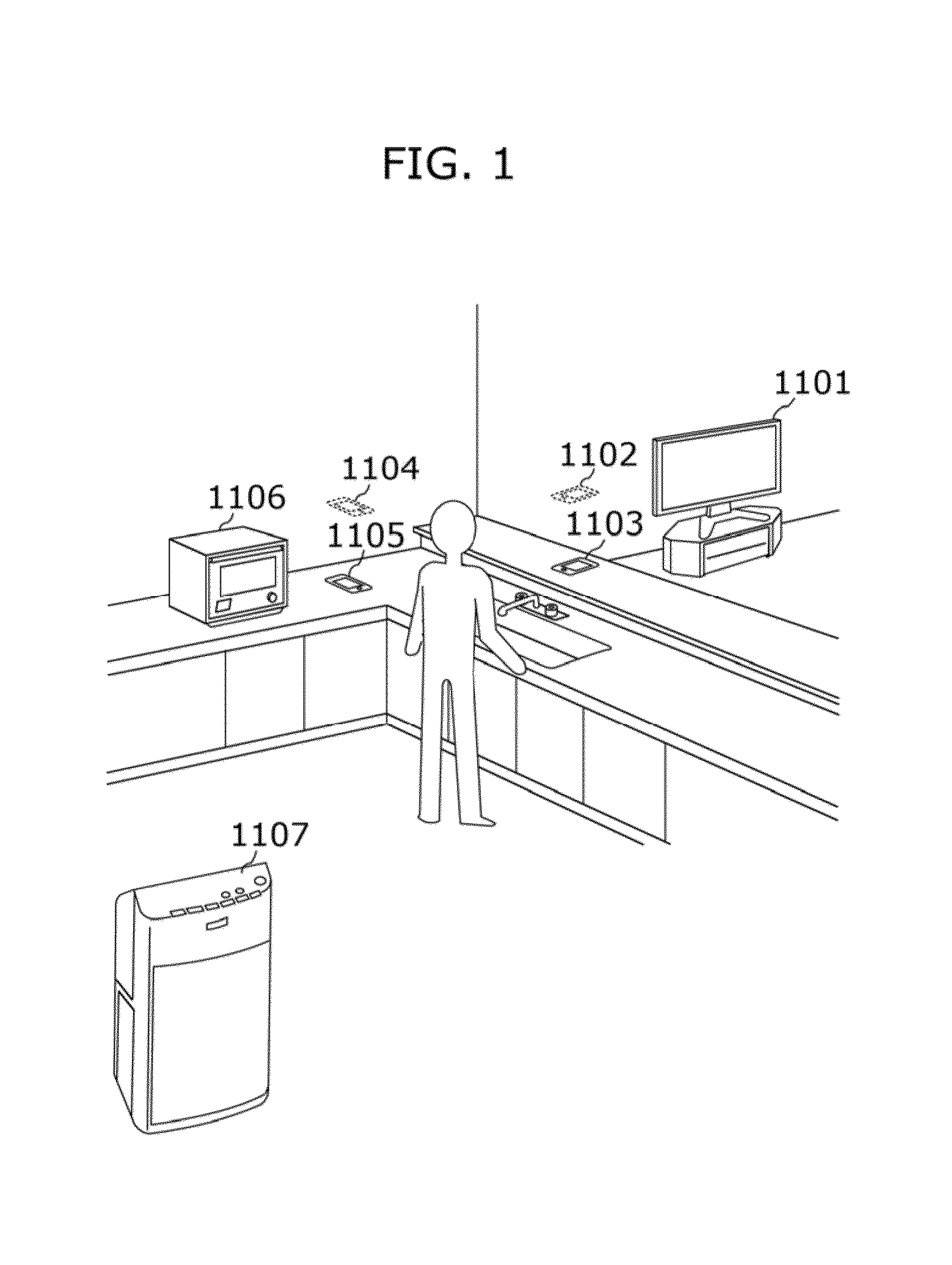
[0490]FIG. 1 is a diagram illustrating an example of the environment in a house in the present embodiment. In the environment illustrated in FIG. 1, there are a television 1101, a microwave 1106, and an air cleaner 1107, in addition to a smartphone 1105, for instance, around a user.

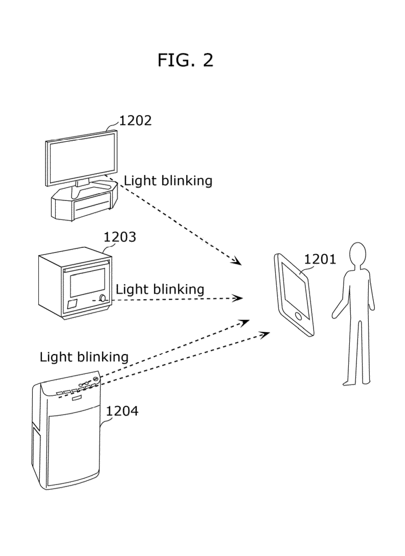
[0491]FIG. 2 is a diagram illustrating an example of communication between the smartphone and the home electric appliances according to the present embodiment. FIG. 2 illustrates an example of information communication, and is a diagram illustrating a configuration in which information output by devices such as the television 1101 and the microwave 1106 in FIG. 1 is obtained by a smartphone 1201 owned by a user, thereby obtaining information. As illustrated in FIG. 2, the devices transmit information using ...

embodiment 2

[0542]In the present embodiment, a description is given, using a cleaner as an example, of the procedure of communication between a device and a user using visible light communication, initial settings to a repair service at the time of failure using visible light communication, and service cooperation using the cleaner.

[0543]FIGS. 10 and 11 are diagrams for describing the procedure of performing communication between a user and a device using visible light according to the present embodiment.

[0544]The following is a description of FIG. 10.

[0545]First, the processing starts from A.

[0546]Next, the user turns on a device in step 2001a.

[0547]Next, in step 2001b, as start processing, it is checked whether initial settings such as installation setting and network (NW) setting have been made.

[0548]Here, if initial settings have been made, the processing proceeds to step 2001f, where normal operation starts, and the processing ends as illustrated by C.

[0549]If initial settings have not be...

embodiment 3

[0604]In the present embodiment, cooperation of devices and Web information using optical communication are described, using a home delivery service as an example.

[0605]The outline of the present embodiment is illustrated in FIG. 15. Specifically, FIG. 15 is a schematic diagram of home delivery service support using optical communication according to the present embodiment.

[0606]Specifically, an orderer orders a product from a product purchase site using a mobile terminal 3001a. When the order is completed, an order number is issued from the product purchase site. The mobile terminal 3001a which has received the order number transmits the order number to an intercom indoor unit 3001b, using NFC communication.

[0607]The intercom indoor unit 3001b, for example, displays the order number received from the mobile terminal 3001a on the monitor of the unit itself, thereby showing to the user that the transmission has been completed.

[0608]The intercom indoor unit 3001b transmits, to an inte...


PUM


Abstract

An information communication method selects between a visible light communication mode in which information is obtained from a subject using an image sensor having a plurality of exposure lines and a normal imaging mode. The method includes obtaining first image data by image capture with a first exposure time in the normal imaging mode. When an image is presented that prompts a user of a terminal device including the image sensor to move the terminal device to enable the information to be obtained, second image data is obtained by image capture with a second exposure time, shorter than the first exposure time, in the visible light communication mode. The information is obtained by demodulating data specified by a direction in a pattern of a bright line appearing in the second image data and corresponding to the exposure lines that is substantially perpendicular to the exposure lines.

Description

CROSS-REFERENCE TO RELATED APPLICATION[0001]The application is a continuation of U.S. application Ser. No. 14 / 087,605 filed Nov. 22, 2013, which claims the benefit of U.S. Provisional Patent Application No. 61 / 746,315 filed on Dec. 27, 2012, Japanese Patent Application No. 2012-286339 filed on Dec. 27, 2012, U.S. Provisional Patent Application No. 61 / 805,978 filed on Mar. 28, 2013, Japanese Patent Application No. 2013-070740 filed on Mar. 28, 2013, U.S. Provisional Patent Application No. 61 / 810,291 filed on Apr. 10, 2013, Japanese Patent Application No. 2013-082546 filed on Apr. 10, 2013, is a continuation-in-part of U.S. Non-Provisional patent application Ser. No. 13 / 902,436 filed on May 24, 2013, and claims benefit of International Patent Application No. PCT / JP2013 / 003319 filed on May 24, 2013, Japanese Patent Application No. 2013-110445 filed on May 24, 2013, U.S. Provisional Patent Application No. 61 / 859,902 filed on Jul. 30, 2013, and Japanese Patent Application No. 2013-158359...

Claims


Application Information

Patent Timeline
Patent Type & Authority Applications(United States)
IPC IPC(8): H04N5/235H04W4/80
CPCH04N5/3532H04B10/1143H04B10/541H04N5/232H04N5/2351H04N5/2353H04N5/243H04W4/001H04N5/2352H04B10/116H04W4/80H04N23/661H04N23/631H04N23/73H04N23/71H04N23/72H04N23/76H04N25/531
Inventor OSHIMA, MITSUAKINAKANISHI, KOJIAOYAMA, HIDEKIFUCHIGAMI, IKUOSHIN, HIDEHIKOMUKAI, TSUTOMUMATSUSHITA, YOSUKEIIDA, SHIGEHIROYAMADA, KAZUNORI
Owner PANASONIC INTELLECTUAL PROPERTY CORP OF AMERICA
Why Eureka
Try Eureka