
Optimum modulator bias systems and methods in coherent optical transmitters

a modulator and bias technology, applied in optics, instruments, electrical equipment, etc., can solve problems such as unsatisfactory optimum points, ungenerating correct constellations, and adding unnecessary costs

Active Publication Date: 2014-10-16
CIENA
View PDF3 Cites 37 Cited by
  • Summary
  • Abstract
  • Description
  • Claims
  • Application Information

AI Technical Summary

Benefits of technology

The patent text describes a method for selecting the optimum phases for a plurality of phase adjusters in an optical modulator system. The method includes steps of selecting a minimum bias point and a half-power bias point for each pair of inner phase adjusters, and setting the inner and outer phase adjusters based on these selections. The method can be performed using a modulator bias selection algorithm that selects the minimum bias point when a phase of a left phase adjuster plus an offset phase adjuster is equal to 0, plus or minus 2, and the method can be performed using a local algorithm that selects the minimum bias point when a phase of a right phase adjuster plus an offset phase adjuster is equal to 0, plus or minus 2, or when a slope of power versus phase is greater than a certain threshold. The method can also include dividing the smaller of the magnitude of the left or right phase adjusters by a feedback controller polarity to set the other phase adjuster. The patent text also describes a coherent optical transmitter system that includes the optical modulator system and a modulator bias controller. The technical effect of the patent text is to provide a more efficient and non-iterative method for selecting the optimum phases for a plurality of phase adjusters in an optical modulator system.

Problems solved by technology

Using lithium niobate modulators, a generalized search can be implemented to find “reasonable” bias points, but these are not necessarily optimum points.
InP technology has a relatively small phase adjustment range and thus, if a poor hardware scheme and algorithm for bias point selection is used, the correct constellation cannot be generated or unnecessary cost is added due to rejected modulators.

Method used


Image

  • Optimum modulator bias systems and methods in coherent optical transmitters
  • Optimum modulator bias systems and methods in coherent optical transmitters
  • Optimum modulator bias systems and methods in coherent optical transmitters

Examples


Embodiment Construction

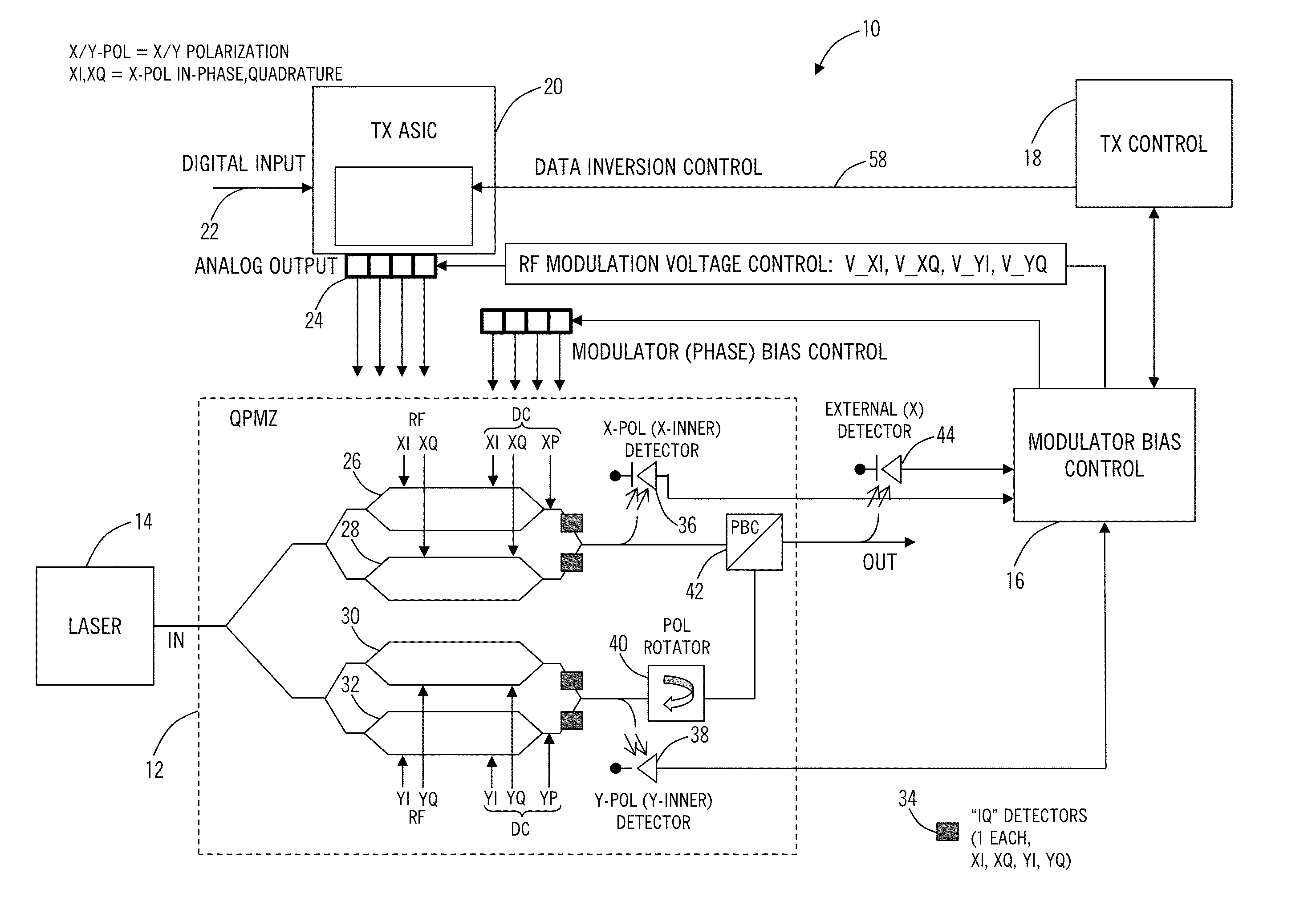
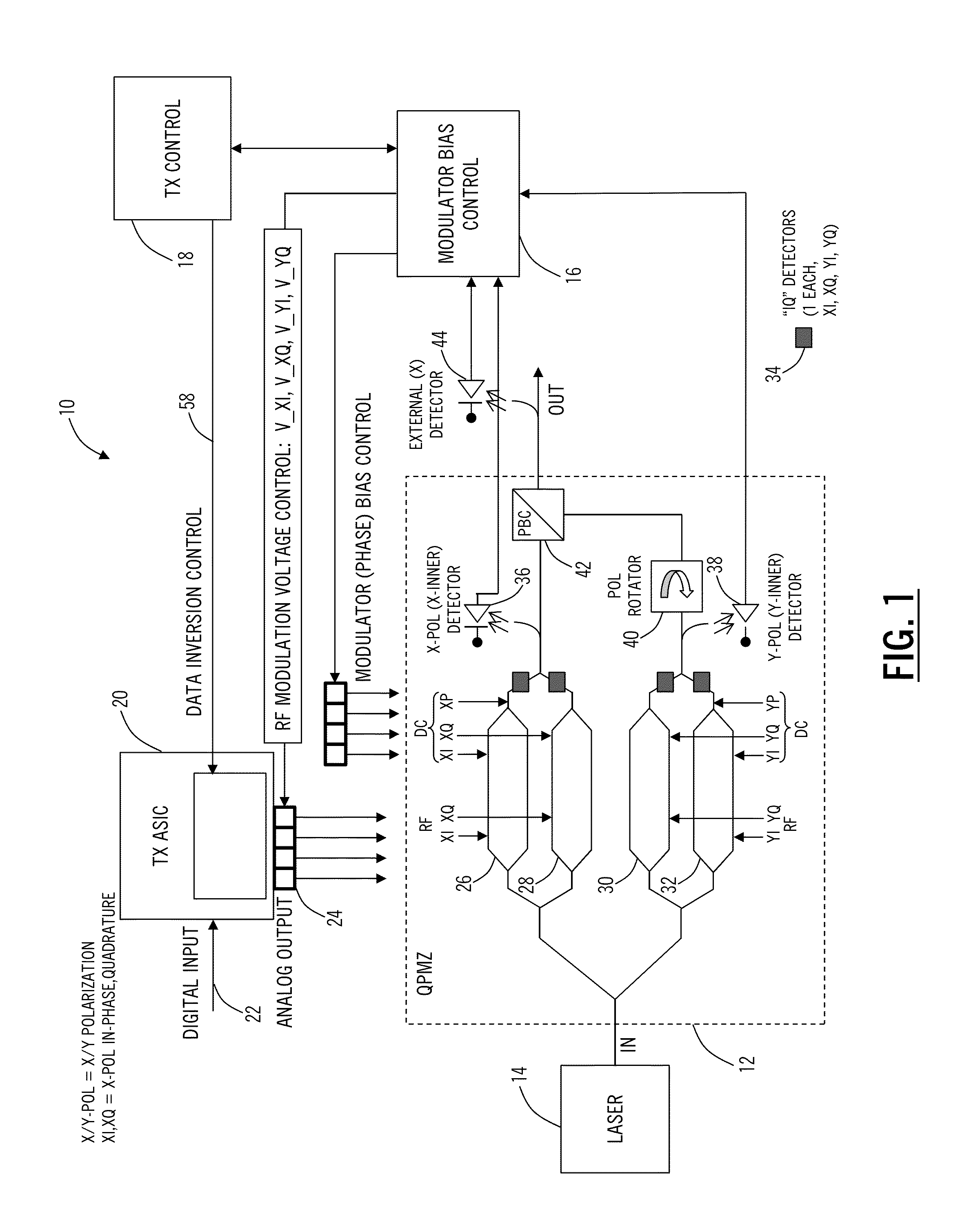
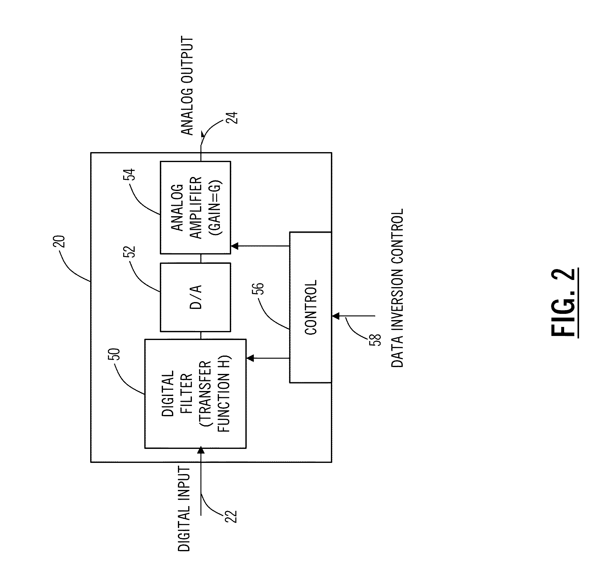
[0016]In various exemplary embodiments, the present disclosure relates to optimum modulator bias systems and methods in coherent optical transmitters. The optimum modulator bias systems and methods solve the problem of generating the correct constellation using the (bias points) with the minimum phase adjustment range. The optimum modulator bias systems and methods include a coherent optical transmitter with control of four (XI, XQ, YI, YQ) quadrature data signals via a transmitter (Tx) application specific integrated circuit (ASIC), with a modulator bias controller which implements an algorithm to find the optimum bias points. The optimum bias points yield a correct constellation with minimum phase / bias adjustment. An algorithm is used to find the optimum bias solution using fast, simple method, adjusting only one quadrature at a time and exploiting a control feature of the Tx ASIC. This algorithm is significantly simpler than a generalized search, is a local algorithm, and uses on...


PUM

PropertyMeasurementUnit
half-power biasaaaaaaaaaa
PHaaaaaaaaaa
PH_PLaaaaaaaaaa

Abstract

A modulator bias selection method, a coherent optical transmitter, and optical modulator solve the problem of generating a correct constellation using the bias points with the minimum phase adjustment range. The optimum modulator bias systems and methods include a coherent optical transmitter with control of four (XI, XQ, YI, YQ) quadrature data signals via a transmitter (Tx) application specific integrated circuit (ASIC), with a modulator bias controller which implements an algorithm to find the optimum bias points. The optimum bias points yield a correct constellation with minimum phase / bias adjustment. An algorithm is used to find the optimum bias solution using fast, simple method, adjusting only one quadrature at a time and exploiting a control feature of the Tx ASIC. This algorithm is significantly simpler than a generalized search, is a local algorithm, and uses only DC power measurement at the transmitter.

Description

FIELD OF THE DISCLOSURE[0001]The present disclosure relates generally to optical communication systems and methods. More particularly, the present disclosure relates to optimum modulator bias systems and methods in coherent optical transmitters.BACKGROUND OF THE DISCLOSURE[0002]In next generation optical modems (e.g., 100 Gb / s and beyond), and in particular in transmitters, there is a requirement for greater optical performance (via better control of optical modulators) and for allowing a wider choice of vendors / technologies (i.e. different lithium niobate (LiNbO3) modulator vendors or indium phosphide (InP) photonic integration technologies). In particular, the new InP technology is prized for its small size and anticipated lower cost (and consequently is proposed to be used in next gen small-form-factor pluggable optics). One of the most important functions of transmitter control is to bias a modulator so it transmits a distortion free and correct optical data constellation via se...

Claims


Application Information

Patent Timeline
Patent Type & Authority Applications(United States)
IPC IPC(8): G02F1/01
CPCH04B10/5161G02F1/01H04B10/50577H04B10/541H04B10/5561G02F1/0123G02F1/2255H04B10/50575H04B10/5055H04B10/532H04B10/548
Inventor MAK, GARYBEAULIEU, YVESSOTOODEH, MOHAMMAD
Owner CIENA
Learn More