Electric push bar assembly
- Summary
- Abstract
- Description
- Claims
- Application Information
AI Technical Summary
Benefits of technology
Problems solved by technology
Method used
Image

Examples
Embodiment Construction
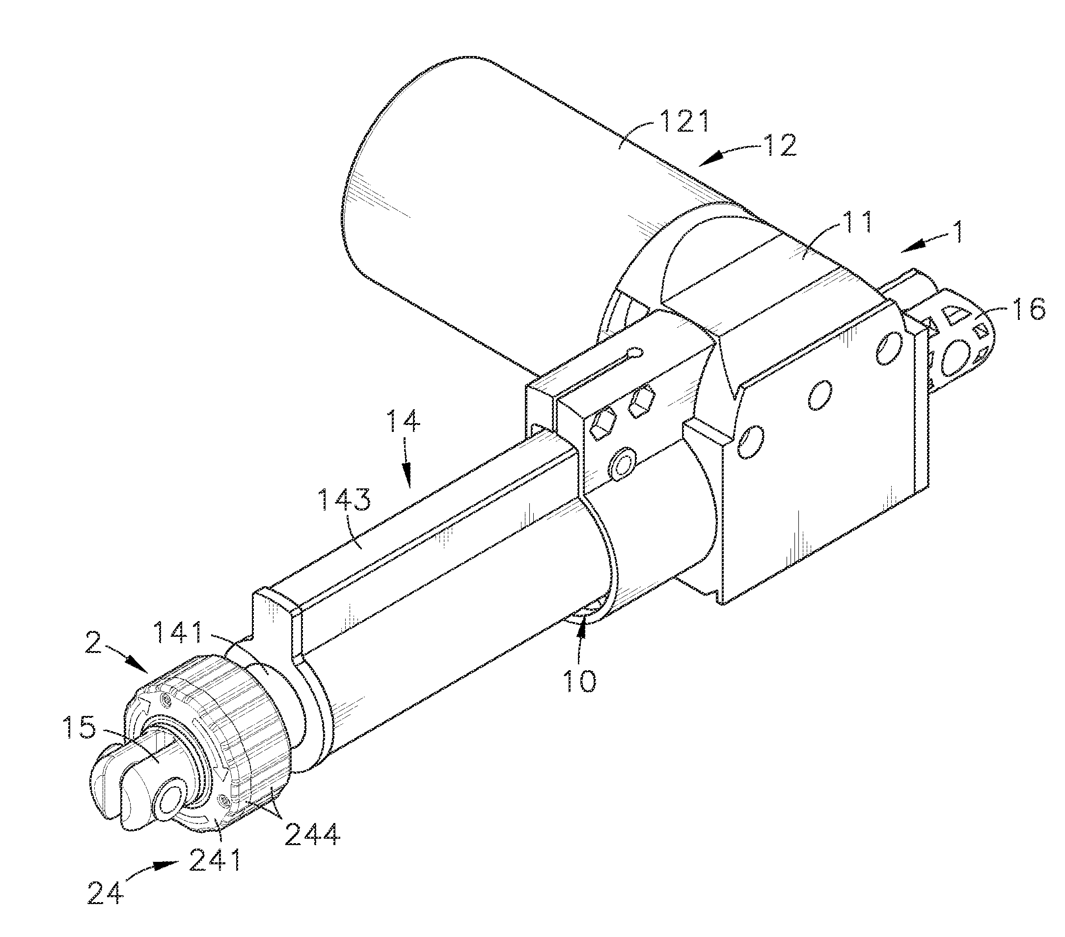
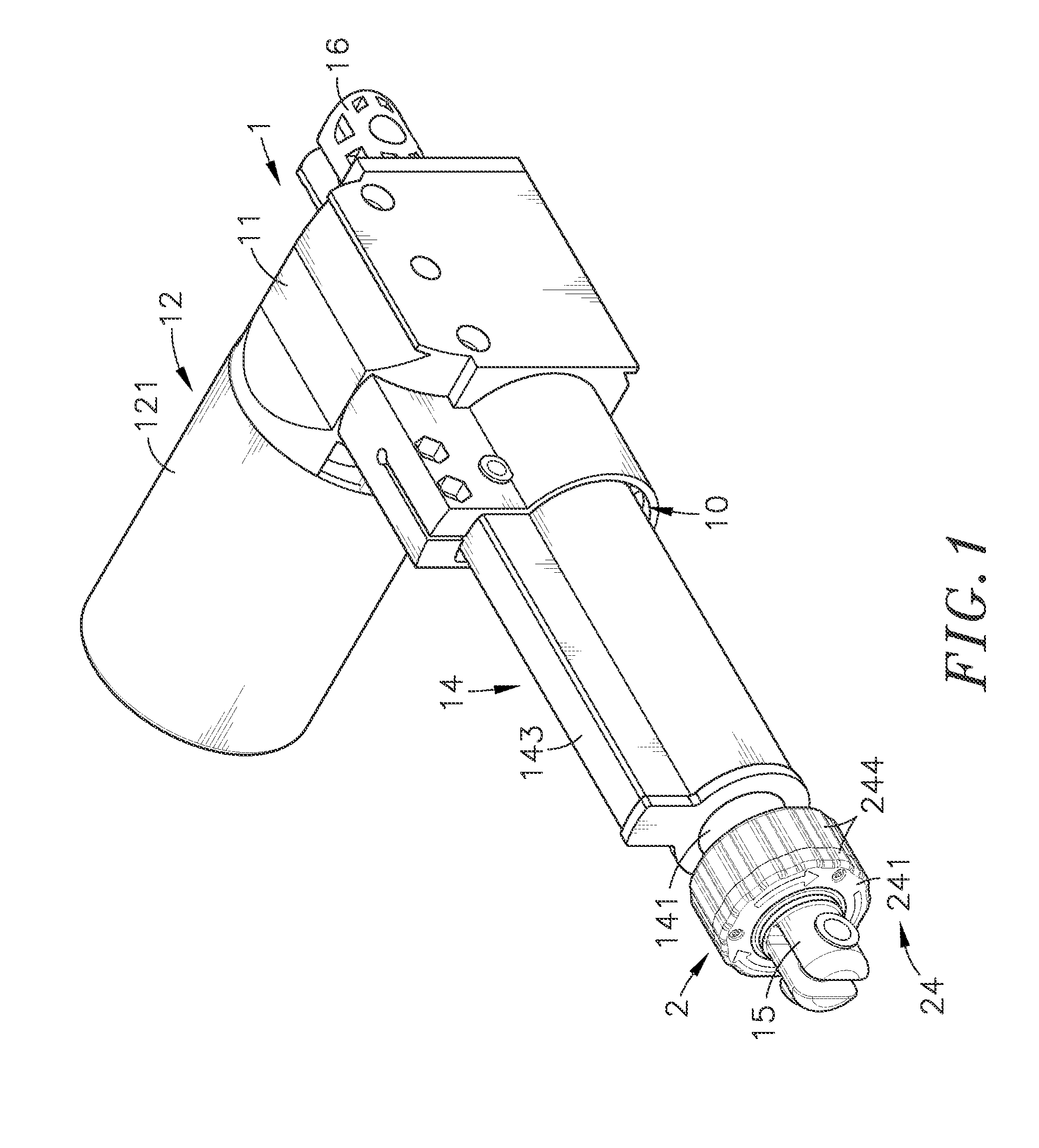
[0026]Referring to FIGS. 1-6, an electric push bar assembly in accordance with the present invention is shown. The electric push bar assembly comprises an electric push bar 1 and a release mechanism 2.
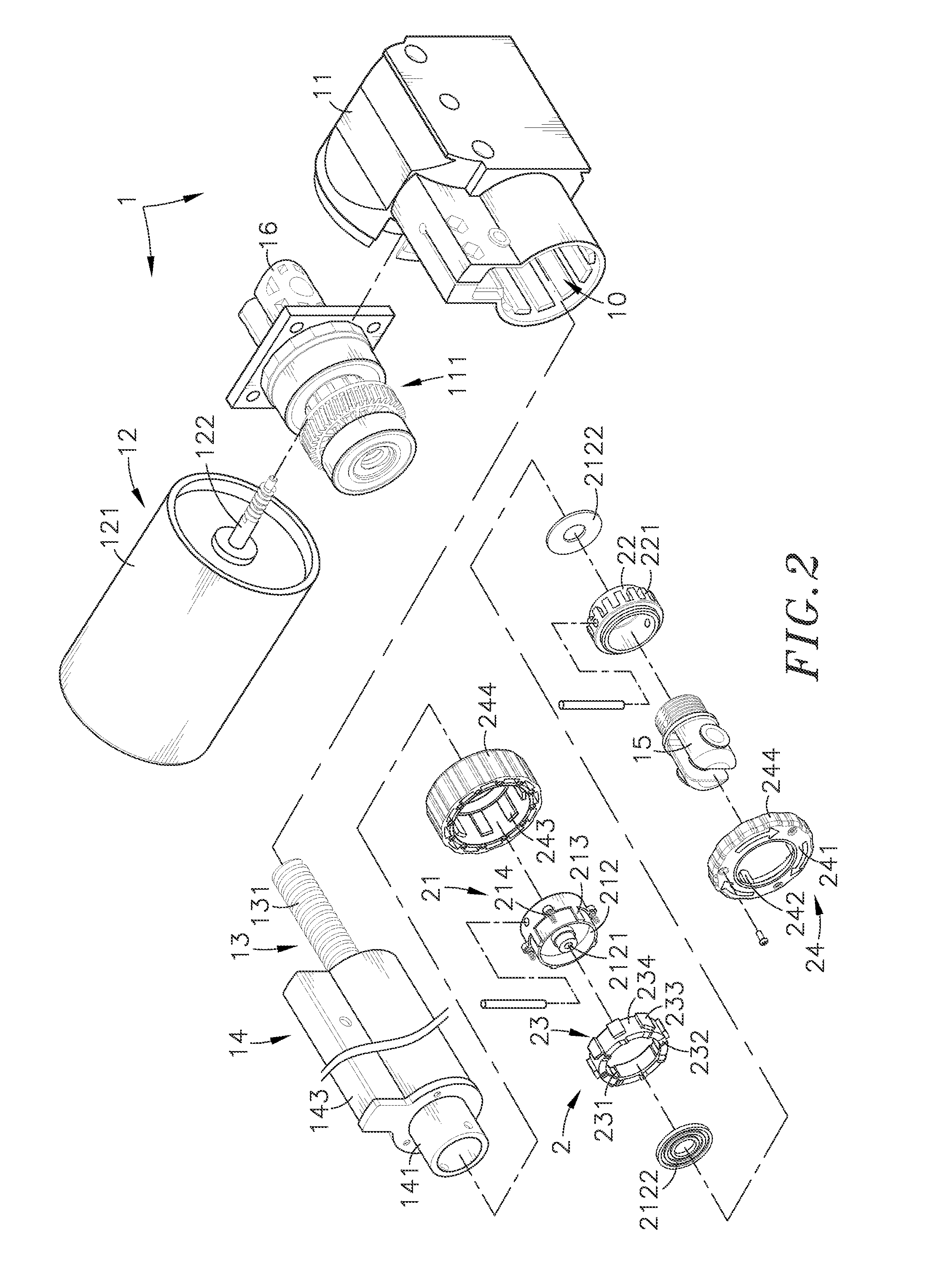
[0027]The electric push bar 1 comprises a shell member 11, a gear set 111, a power drive 12, a transmission mechanism 13, a retractable tube 14, a connector 15, and a mounting member 16. The shell member 11 defines therein an accommodation chamber 10 that accommodates the gear set 111. The power drive 12 comprises a motor 121 affixed to the shell member 11, and a drive shaft 122 meshed with the gear set 111 and rotatable by the motor 121. The transmission mechanism 13 comprises a transmission screw 131 connected to and rotatable by the gear set 111. The retractable tube 14 is coupled to and movable by the transmission screw 131 of the transmission mechanism 13. The connector 15 is connected to one end of the retractable tube 14 opposite to the transmission screw 131 of the transmission...
PUM
 Abstract
Description
Claims
Application Information
 - Generate Ideas
- Intellectual Property
- Life Sciences
- Materials
- Tech Scout
- Unparalleled Data Quality
- Higher Quality Content
- 60% Fewer Hallucinations
Browse by: Latest US Patents, China's latest patents, Technical Efficacy Thesaurus, Application Domain, Technology Topic, Popular Technical Reports.
© 2025 PatSnap. All rights reserved.Legal|Privacy policy|Modern Slavery Act Transparency Statement|Sitemap|About US| Contact US: help@patsnap.com