
Gasket, reactor using the same for spiral sealing and manufacturing method thereof

Active Publication Date: 2011-02-03
SEWON CELLONTECH
View PDF4 Cites 0 Cited by
  • Summary
  • Abstract
  • Description
  • Claims
  • Application Information

AI Technical Summary

Benefits of technology

[0020]According to a reactor using a gasket for sealing a spiral, a manufacturing method thereof, and a gasket therefor of the present invention, since the gasket 10 is fittingly coupled to the outer circumference of the spirals positioned between the inner pipe 1 and the outer pipe 2 to form a flow path for a heat medium, the assembly of coaxially arranging the inner pipe 1 and the outer pipe 2 is facilitated. That is, after the spirals 3 are installed on the outer circumference of the inner pipe 1 and the gasket 10 is assembled to the spirals 3, the outer pipe 2 is press-fitted onto the inner pipe 1. Thus, through the above sequential assembly, the fabrication of the reactor 100 is facilitated which includes the shell 120 formed by assembling the inner pipe 1 and the outer pipe 2 in a coaxial arrangement. Particularly, the gasket 10 includes the frame 20 and the cushion plate 40 whereby the both lateral sides 24 of the frame 20 are fittingly coupled to both circumferential outer sides of the spirals 3 such that the cushion plate 40 abuts against the outer circumference of the spirals 3 in a state in which the spirals 3 are inserted into the channel 21. Accordingly, additional processing of the spirals 3 is not needed, the assembly is facilitated, breakage of the gasket (10) during assembly of the outer pipe (2) is effectively prevented and the post-assembly seal between the spiral (3) and the outer pipe (2) is stabilized.

Problems solved by technology

However, such a conventional reactor 100 entails a problem in that production efficiency decreases due to an increase in the amount of secondary processing works for assembling the outer pipe 2 and the spirals 3, in that the assembly work is difficult, in that the risk of breakage of the spirals 3 and the outer pipe 2 during the assembly is high, and in that a secondary defect occurs after the completion of the assembly.

Method used


Image

  • Gasket, reactor using the same for spiral sealing and manufacturing method thereof
  • Gasket, reactor using the same for spiral sealing and manufacturing method thereof
  • Gasket, reactor using the same for spiral sealing and manufacturing method thereof

Examples


Embodiment Construction

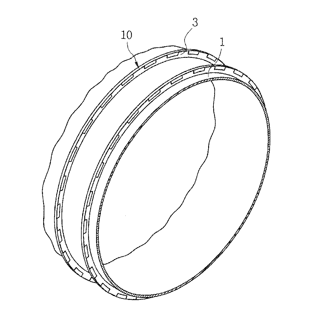
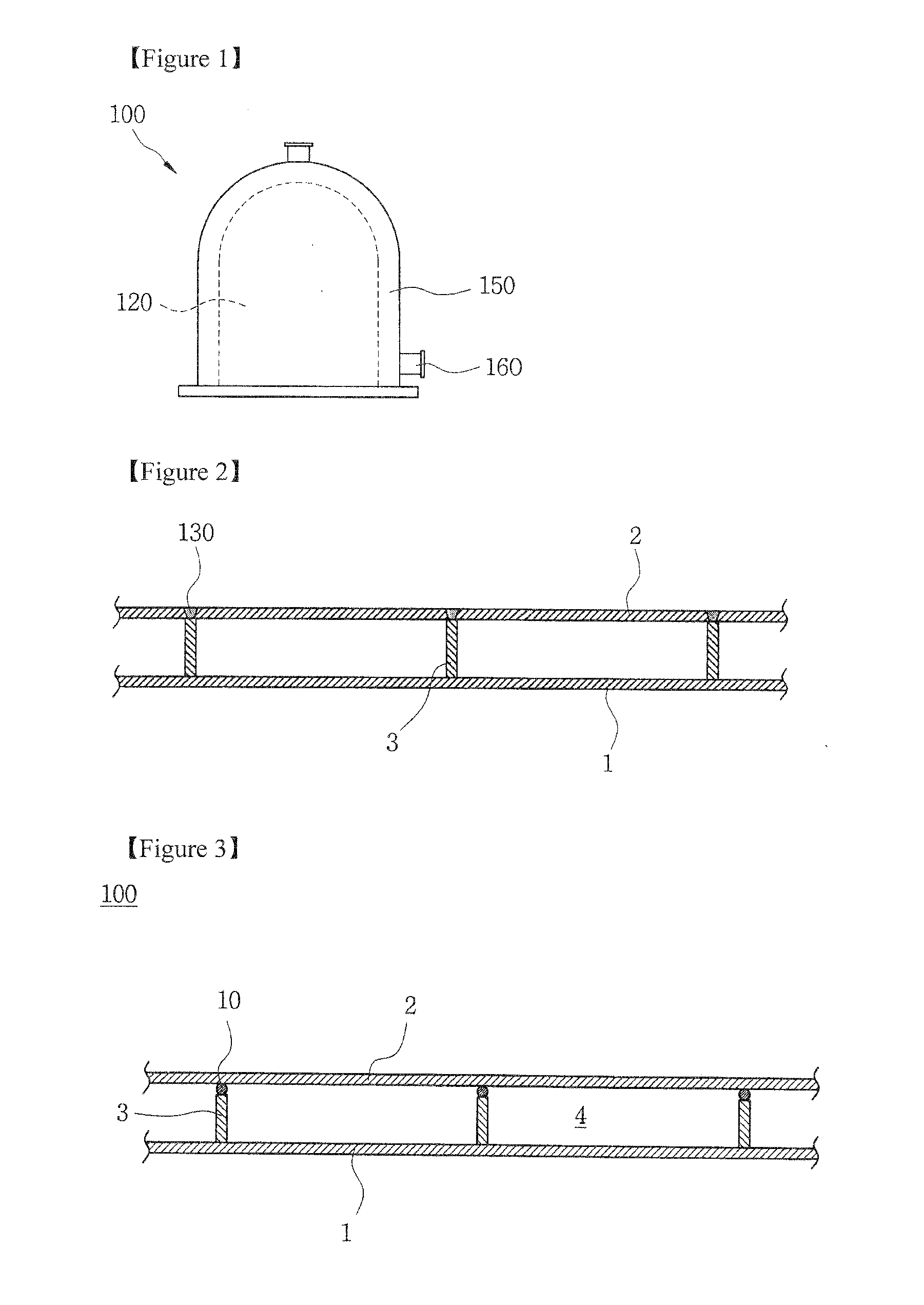
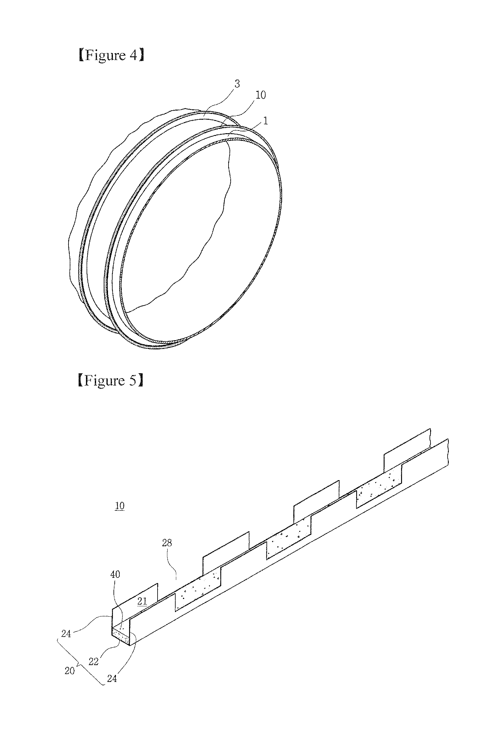
[0030]FIG. 3 is a diagrammatic view showing the main elements of a reactor using a gasket for spiral sealing and a gasket therefor according to the technical spirit of the present invention, and FIG. 4 is a perspective view showing a manufacturing method of a reactor using a gasket for spiral sealing according to the technical spirit of the present invention.

[0031]Referring to FIGS. 3 and 4, the reactor 100 according to the present invention is characterized in that since the gasket 10 is fittingly coupled to the outer circumference of the spirals positioned between the inner pipe 1 and the outer pipe 2 to form a flow path for a heat medium, the assembly of coaxially arranging the inner pipe 1 and the outer pipe 2 is facilitated. That is, in the reactor 100 using a gasket for spiral sealing, a shell 120 and a jacket 150 are coupled to each other. In this case, the shell and jacket include a nozzle 160 mounted respectively thereon for allowing fluid to be introduced into and discharg...


PUM

PropertyMeasurementUnit
Structureaaaaaaaaaa

Abstract

Provided are a gasket, a reactor using the same for sealing a spiral, and a manufacturing method thereof. The present invention improves a spiral sealing mechanism of a reactor wherein, spirals are continuously installed in the longitudinal direction between an inner pipe and an outer pipe coaxially arranged to form a flow path for a heat medium, so the seal between the spiral and the outer pipe is stably maintained and fabrication of the reactor is facilitated. The gasket (10) according to the present invention has a structure that the gasket is inserted in and coupled with the spiral (3), and thus does not need additional processing for combining the gasket (10). Therefore, since the gasket (10) and spiral (3) are coupled by lodging the spiral (3) into a channel (21) of the gasket (10), the assembly is facilitated. Furthermore, since the gasket (10) is evenly coupled in the outer circumference of the spiral (3), in which a cushion plate (40) made of resilient material is installed, breakage of the gasket (10) during assembly of the outer pipe (2) is effectively prevented and the post-assembly seal between the spiral (3) and the outer pipe (2) is stabilized.

Description

TECHNICAL FIELD[0001]The present invention relates to a gasket, a reactor using the gasket for sealing a spiral, and a manufacturing method of the reactor. More specifically, the present invention relates to an improvement of a spiral sealing mechanism of a reactor wherein spirals are continuously installed in the longitudinal direction between an inner pipe and an outer pipe coaxially arranged to form a flow path for a heat medium, so that the seal between the spiral and the outer pipe is effectively maintained and fabrication of the reactor is facilitated.BACKGROUND ART[0002]A reactor or a high-pressure reactor is process equipment which is manufactured in various forms and is widely used in facilities like gas plants, refineries, alternative energy plants, chemical plants and power plants. Such a reactor is a device in which a chemical reaction occurs in a production process, and thus it is required that the reactor be designed in consideration of both a chemical resistance again...

Claims


Application Information

Patent Timeline
IPC IPC(8): B01J19/00B23P11/00F16J15/02
CPCF28F2230/00B01J3/002B01J19/0073F28D7/106Y10T29/49874Y10T29/49826Y10T29/49872Y10T29/4987Y10T29/49879F28F1/36
Inventor SEO, GYU HYUN
Owner SEWON CELLONTECH
Learn More