
Squeegee for printing device, printing device, and printing method

Inactive Publication Date: 2009-10-15
YAMAHA MOTOR CO LTD
View PDF0 Cites 2 Cited by
  • Summary
  • Abstract
  • Description
  • Claims
  • Application Information

AI Technical Summary

Benefits of technology

[0008]The invention was devised in view of the foregoing, and has an object to provide a squeegee for a printing device that not only achieves a satisfactory scraping ability but also facilitates the fabrication at a low cost, and a printing device and a printing method using the squeegee.

Problems solved by technology

However, in the half etching portion having a hollow, it is particularly difficult to press the squeegee against the mask surface and let the squeegee follow along the mask surface precisely.
Such being the case, the technique to increase the bending elasticity by merely making the squeegee tip end thinner as in the conventional squeegee disclosed in Patent Document 1 fails to ensure a sufficient following ability of the squeegee with respect to the stencil, which poses a problem that it is difficult to achieve a satisfactory scraping ability.
This poses another problem that not only the fabrication becomes difficult, but also the cost is increased.

Method used


Image

  • Squeegee for printing device, printing device, and printing method
  • Squeegee for printing device, printing device, and printing method
  • Squeegee for printing device, printing device, and printing method

Examples


experiment example 1

[0048]Hereinafter, an experiment example relating to technical significance of limiting numerical values for the squeegee of the invention will be described.

[0049]A squeegee sample having a thinned tip end was prepared using stainless steel (SUS 420) with 10-μm-thick Ni / P-plating as a squeegee material (horizontal length of 351.5 mm, the height of 40 mm, and the thickness of 0.22 mm) by applying a machining process to grind the lower edge (tip end) on one surface side (back side) alone. Herein, squeegee samples were prepared by varying the thickness Ta of the thinned tip end by 10 μm in a range of 40 to 140 μm. The length La of the thinned tip end of each squeegee sample was set constant at 1.5 mm.

[0050]A half etching mask was set in a printing device same as the printing device of the embodiment above. The respective squeegee samples were then set successively and printing was performed using each sample.

[0051]The size (area) of the CSP portion of the half matching mask set in the ...

experiment example 2

[0054]Squeegee samples were prepared by applying a process in the same manner as above to a squeegee material same as the one described above while varying the length La of the thinned tip end by 0.1 mm within a range of 0.1 to 3.3 mm. The thickness Ta of the thinned tip end of each squeegee sample was set constant at 50 μm.

[0055]Also, as in the same manner as above, printing was performed using each squeegee sample and the thickness (μm) of solder cream left unscraped in the CSP portion was measured for each squeegee sample. A relation of the length (mm) of the thinned tip end of the squeegee and the thickness (μm) of the unscraped solder is set forth in FIG. 6 in the form of a graph.

[0056]As is obvious from the graph, in a case where a squeegee having the length La of the thinned tip end of 0.5 mm or greater was used, substantially no thickness of unscraped solder was confirmed. Hence, the squeegee tip end was able to come inside the CSP portion in a reliable manner and scraped th...


PUM


Abstract

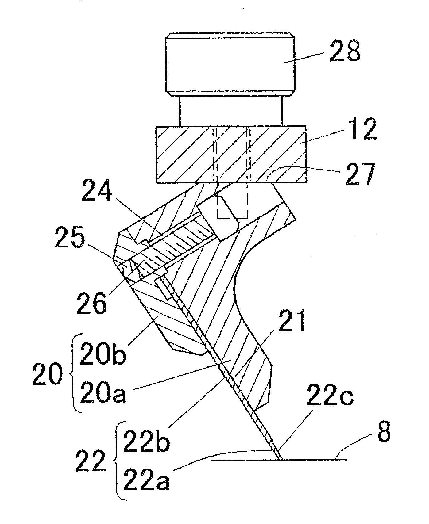
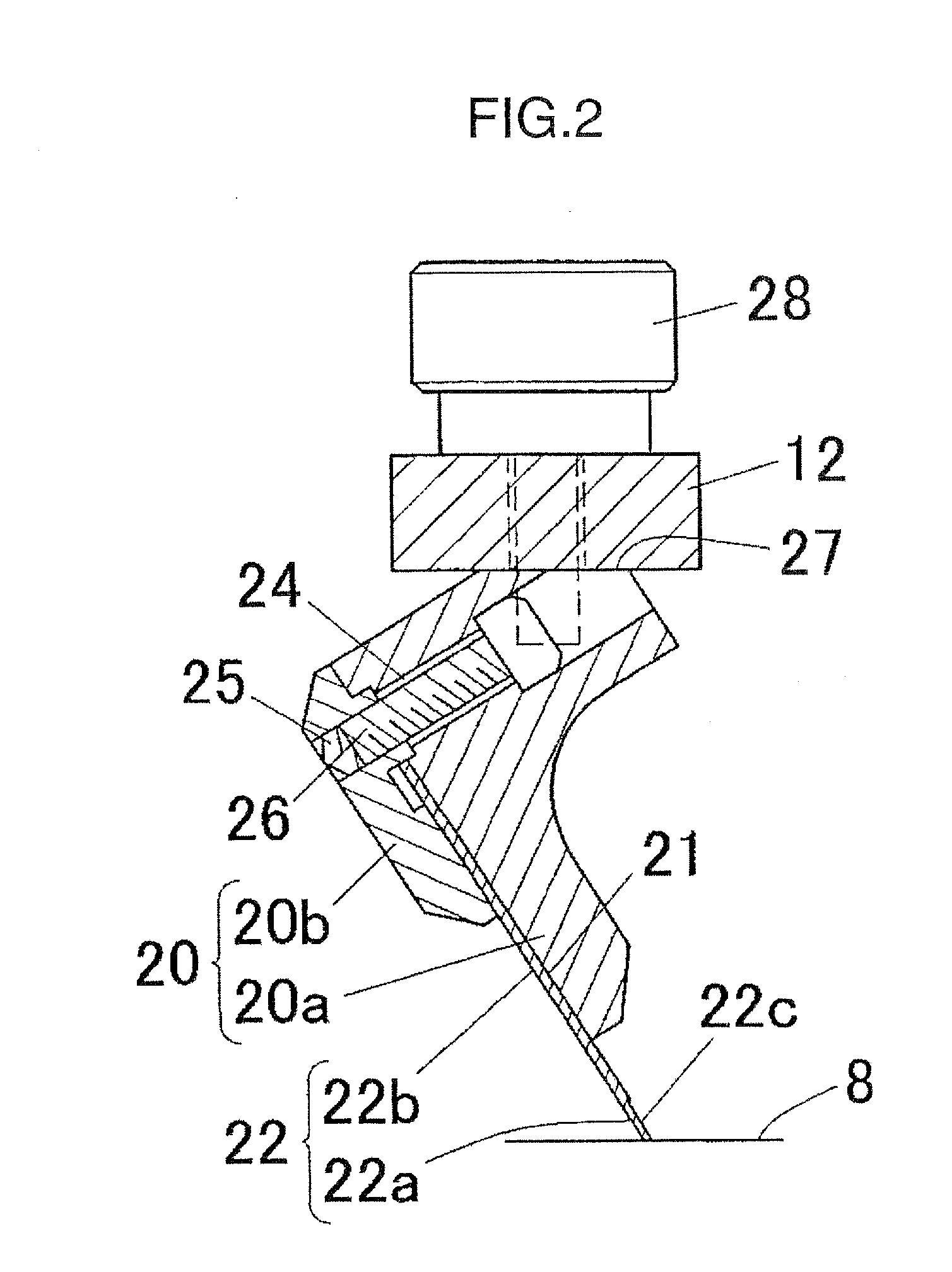
[Problems] To provide a squeegee for a printing device that achieves a satisfactory scraping ability and is readily fabricated at low costs.[Means for Solving the Problems] A squeegee for a printing device applies paste on a stencil 7 onto a substrate W by spreading the paste by sliding a tip end 22a along a surface of the stencil 7 disposed on the substrate W. The squeegee is formed of an expanded material made of iron and steel, and the tip end 22a is made thinner by applying a machining process to one surface alone. A thickness Ta of the tip end 22a made thinner is set to 40 to 120 μm and a length La thereof is set to 0.5 mm or greater.

Description

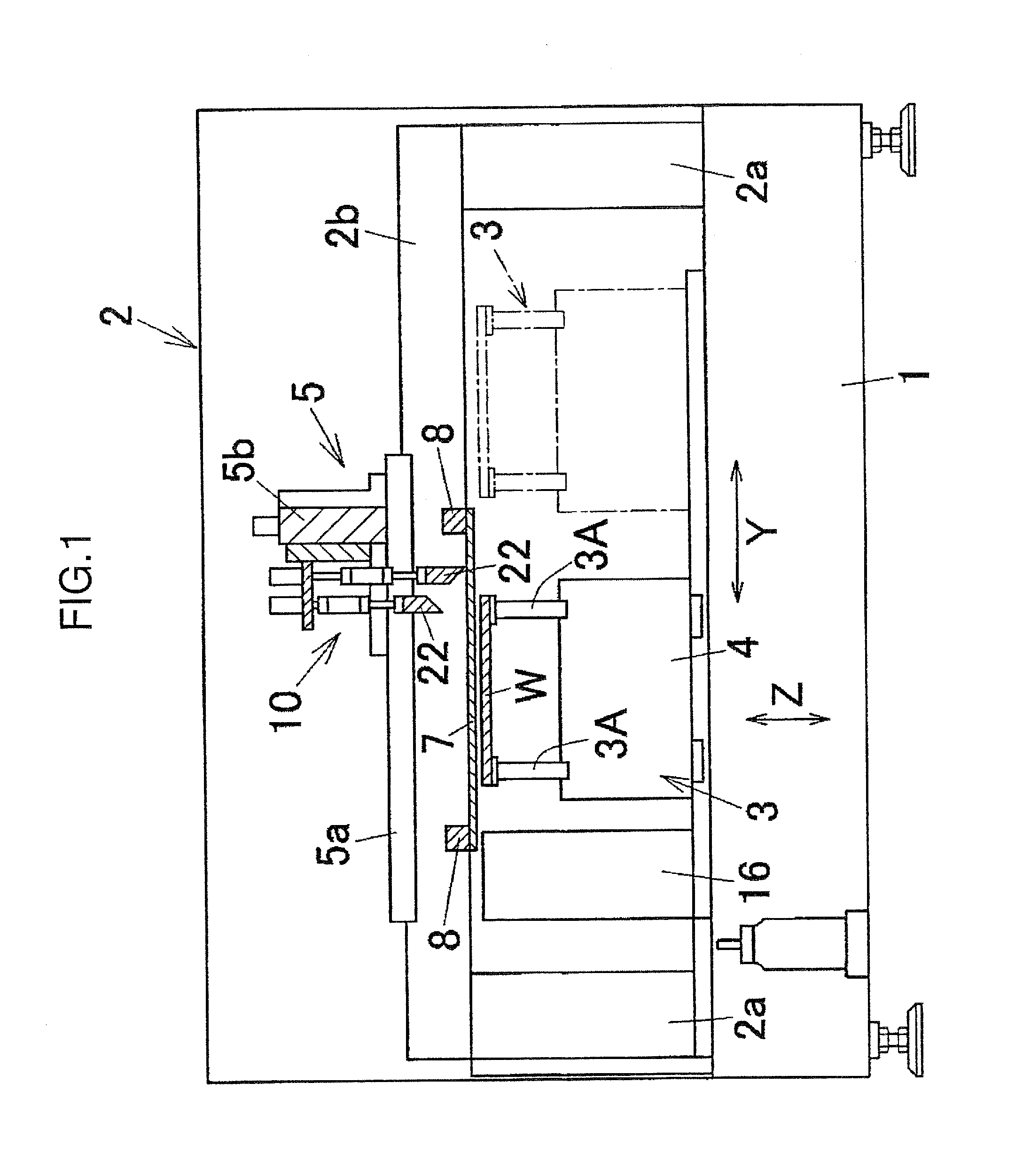
TECHNICAL FIELD[0001]The present invention relates to a squeegee for a printing device that makes prints on a substrate by spreading paste on a stencil, a printing device, and a printing method.BACKGROUND ART[0002]There is a screen printing device configured in such a manner that a stencil (mask) for screen printing is superimposed on a substrate set at the printing position and paste, such as cream solder, supplied on the stencil is scraped and spread by the squeegee, so that the paste is printed (applied) onto the substrate at predetermined positions via openings (pattern holes) made in the stencil.[0003]Of the printing devices of this type, the one disclosed, for example, in Patent Document 1 makes the tip end of the squeegee for scraping the cream solder thinner than the base end to increase the bending elastic coefficient at the squeegee tip end, so that the squeegee tip end achieves a better following ability with respect to the stencil. Even in the presence of winding (bendin...

Claims


Application Information

Patent Timeline
IPC IPC(8): B05C17/06
CPCB41F15/44H05K2203/0139H05K3/1233
Inventor KUSUNOKI, TOSHIYUKISATO, TAKAOSUZAWA, HIDEKI
Owner YAMAHA MOTOR CO LTD
Learn More