Directional Lambertian Optic Illumination Apparatus

Inactive Publication Date: 2011-03-17
THE UNITED STATES OF AMERICA AS REPRESENTED BY THE SECRETARY OF THE NAVY
View PDF3 Cites 0 Cited by
  • Summary
  • Abstract
  • Description
  • Claims
  • Application Information

AI Technical Summary

Benefits of technology

[0003]Various details of the present disclosure are hereinafter summarized to facilitate a basic understanding, where this summary is not an extensive overview of the disclosure, and is intended neither to identify certain elements of the disclosure, nor to delineate the scope thereof. Rather, the primary purpose of this summary is to present some concepts of the disclosure in a simplified form prior to the more detailed description that is presented hereinafter. Improved illumination apparatus is provided which includes a Lambertian (or quasi-Lambertian) light source with an emitter side, as well as a reflector structure having an output side and a reflective surface with a concave parabolic contour that reflects light from the emitter side of the light source t

Problems solved by technology

True Lambertian uniformity may not be achieved in some practical applications, but devices approaching such uniformity are termed “quasi-Lambertian”.
Coupling light from a plane Lambertian or quasi-Lambertian emitter, such as an LED die, into a more restricted angular distribution ca

Method used


Image

  • Directional Lambertian Optic Illumination Apparatus
  • Directional Lambertian Optic Illumination Apparatus
  • Directional Lambertian Optic Illumination Apparatus

Examples


Example

[0021]One or more embodiments or implementations are hereinafter described in conjunction with the drawings, where like reference numerals are used to refer to like elements throughout, and where the various features are not necessarily drawn to scale.

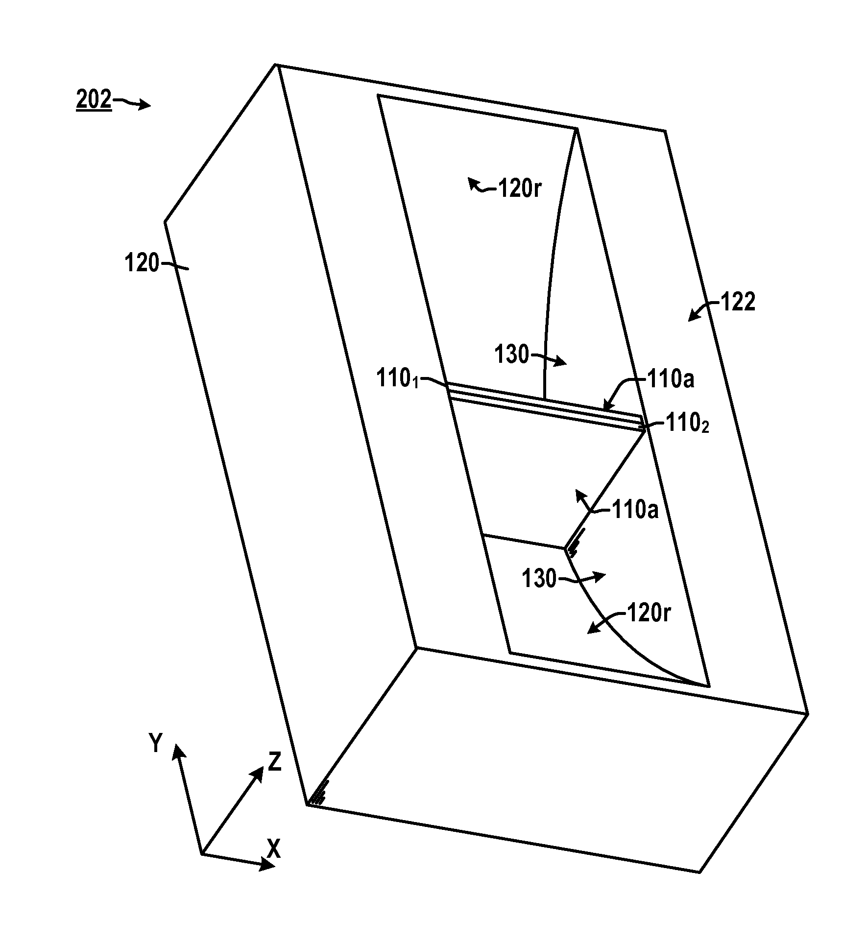
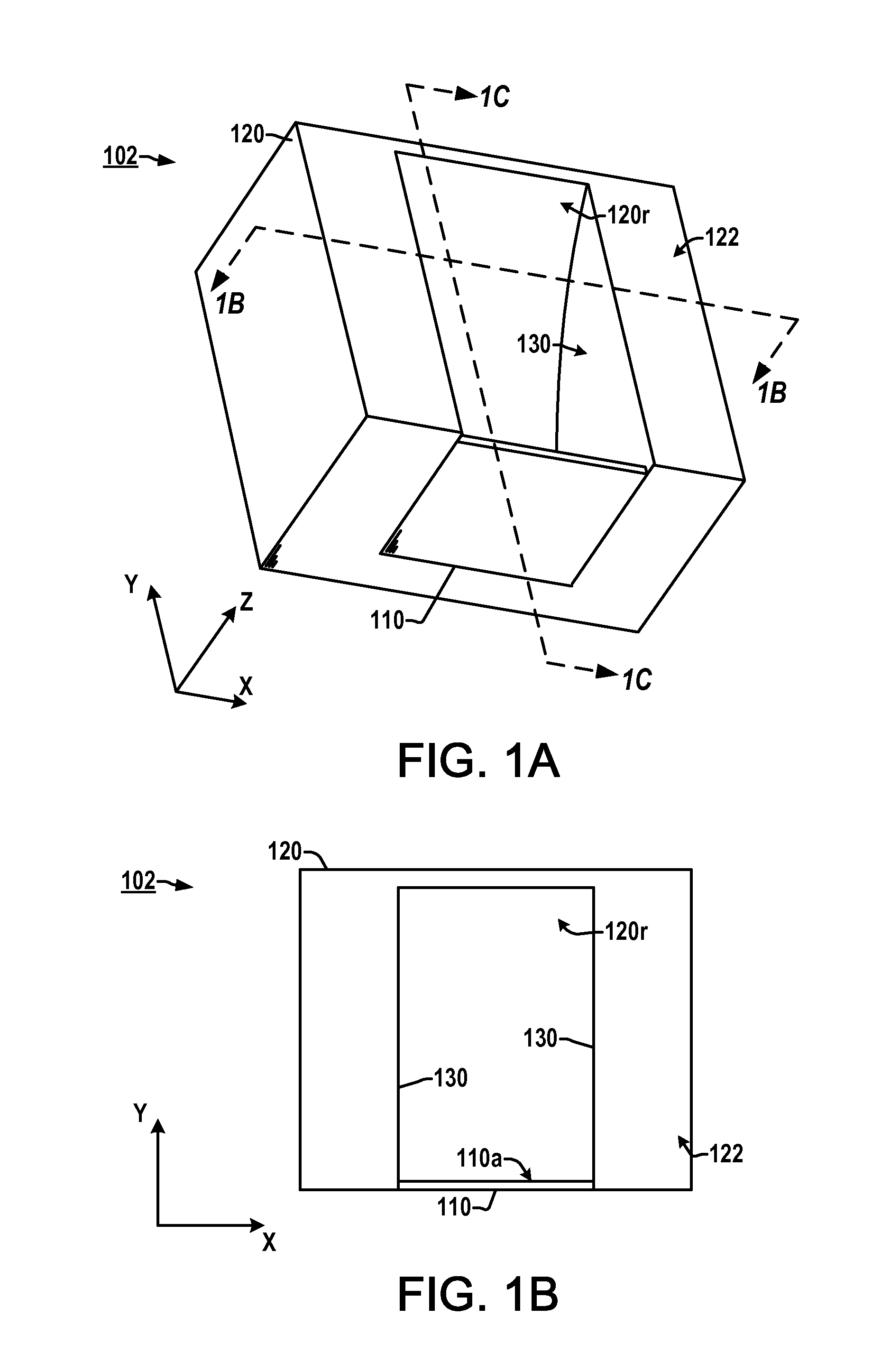
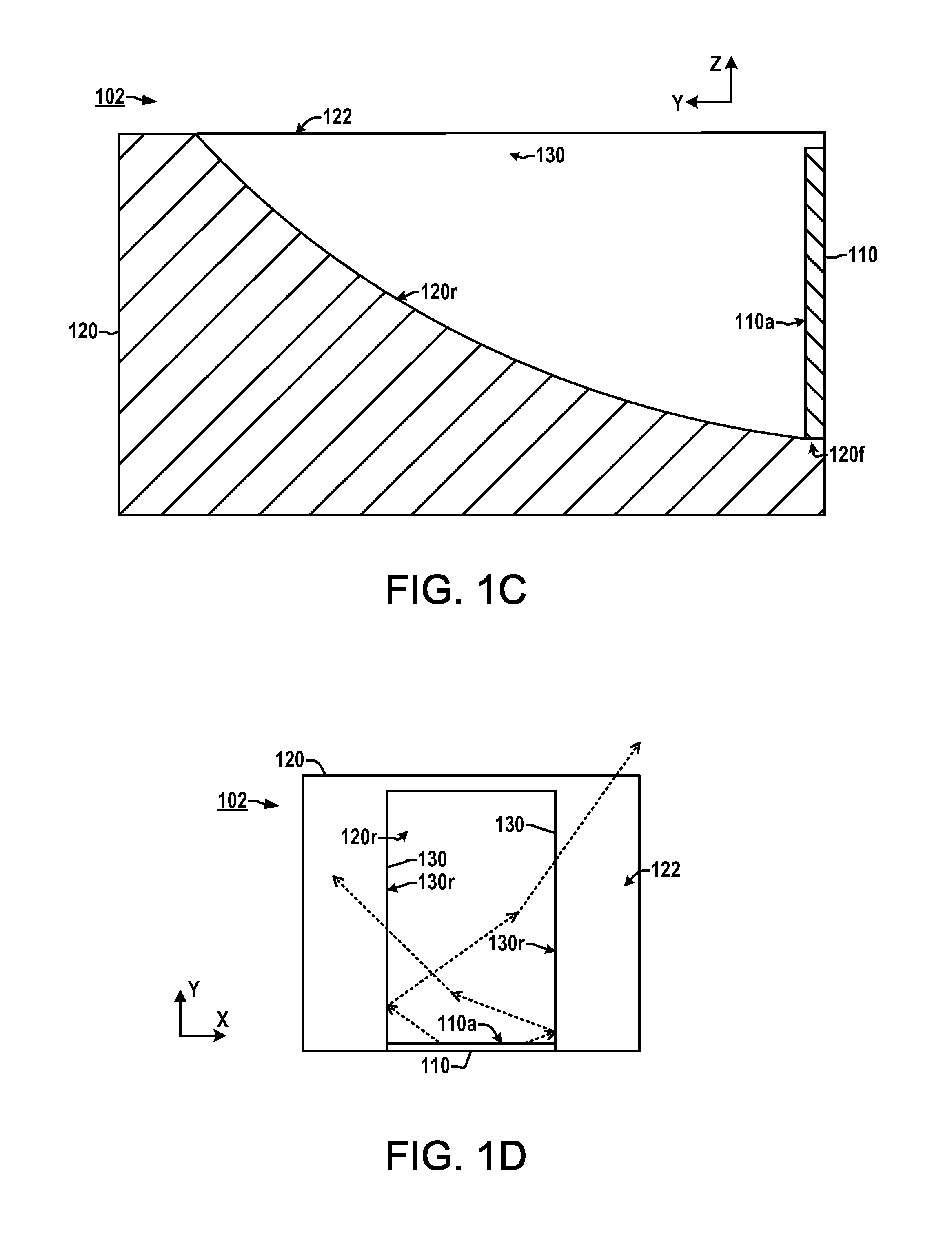
[0022]Referring initially to FIGS. 1A-1G, an exemplary directional Lambertian lighting apparatus 102 is illustrated including a Lambertian (or quasi-Lambertian) light source 110 with an emitter side 110a facing at least a portion of a parabolic reflective surface 120r of a reflector structure 120. The apparatus 102 provides Lambertian or quasi-Lambertian output light 150 (FIG. 1E) over an angular dispersion range less than 180 degrees. As best shown in FIGS. 1A-1C, the light source 110 can be any suitable source of Lambertian or substantially Lambertian (quasi-Lambertian) light, such as an LED source, which has at least one emitter side 110a from which Lambertian or quasi-Lambertian light is emitted in operation. In the illustrated emb...


PUM


Abstract

A lighting apparatus is presented, having a Lambertian or quasi-Lambertian light source with an emitter side, as well as a reflector structure having an output side and a reflective surface with a concave parabolic contour that reflects light from the emitter side of the light source to provide Lambertian or quasi-Lambertian output light from the output side.

Description

FIELD OF THE DISCLOSURE[0001]The present disclosure relates generally to optical illumination and more particularly to apparatus for directional Lambertian optic illumination.BACKGROUND[0002]Lambertian illumination provides uniform radiance for different angles of observation such that all points of an illuminated area are uniformly illuminated from all directions. True Lambertian uniformity may not be achieved in some practical applications, but devices approaching such uniformity are termed “quasi-Lambertian”. Planar Lambertian (or planar quasi-Lambertian) sources typically emit light of uniform intensity throughout a 180 degree angular dispersion pattern. In certain applications, however, it is desirable to reduce the angular extent of the Lambertian light, such as ship navigational lighting where a beacon needs to be restricted to a well-defined solid angle while retaining uniform brightness with angle (Lambertian) properties, as well as area lighting applications. Coupling ligh...

Claims


Application Information

Patent Timeline
IPC IPC(8): F21V7/06
CPCF21V7/0025F21V7/06G02B19/0061G02B19/0071G02B19/0023F21Y2101/02F21Y2115/10
Inventor LEBOW, PAUL S.SNAIL, KEITH A.
Owner THE UNITED STATES OF AMERICA AS REPRESENTED BY THE SECRETARY OF THE NAVY
Why Eureka
Try Eureka