Non-contact tonometer

a tonometer and non-contact technology, applied in the field of tonometers, can solve the problems of complicated control circuits, difficult to stop the piston at a target position, annoying objects, etc., and achieve the effect of suppressing unnecessary puffing and simple arrangemen

Inactive Publication Date: 2014-10-23
CANON KK
View PDF1 Cites 6 Cited by
  • Summary
  • Abstract
  • Description
  • Claims
  • Application Information

AI Technical Summary

Benefits of technology

[0015]The present invention solves the above-described problems, and provides a non-contact tonometer capable of suppressing puffing of unnecessary air against an eye to be inspected by a low-cost, simple arrangement.
[0017]The non-contact tonometer according to the present invention can puff an optimum amount of air in accordance with an eye pressure value by changing the position of the opening portion formed in the outer wall of the cylinder. Even when the piston is controlled by driving the solenoid, puffing of air unnecessary for measurement caused by the inertial force of the piston can be prevented.
[0018]The non-contact tonometer according to the present invention can be configured by only adding the opening portion and opening portion position selection system to a conventional apparatus. Thus, a low-cost, compact apparatus can be provided.

Problems solved by technology

This makes it difficult to stop the piston at a target position.
However, owing to the inertial force of the piston, unnecessary air is puffed against the eye, annoying the object.
If the applied voltage is designed to be variable, the control circuit becomes complicated.
However, to instantaneously release pressurized air from the cylinder, the opening of the electromagnetic valve needs to be much larger than the nozzle, so a large electromagnetic valve is required.
The large electromagnetic valve costs, and it is difficult to mount the large electromagnetic valve in a limited space inside the apparatus.
This raises the hurdle for employing this method.
A control circuit for controlling the electromagnetic valve in such a short time becomes complicated and expensive.

Method used


Image

  • Non-contact tonometer
  • Non-contact tonometer
  • Non-contact tonometer

Examples


first embodiment

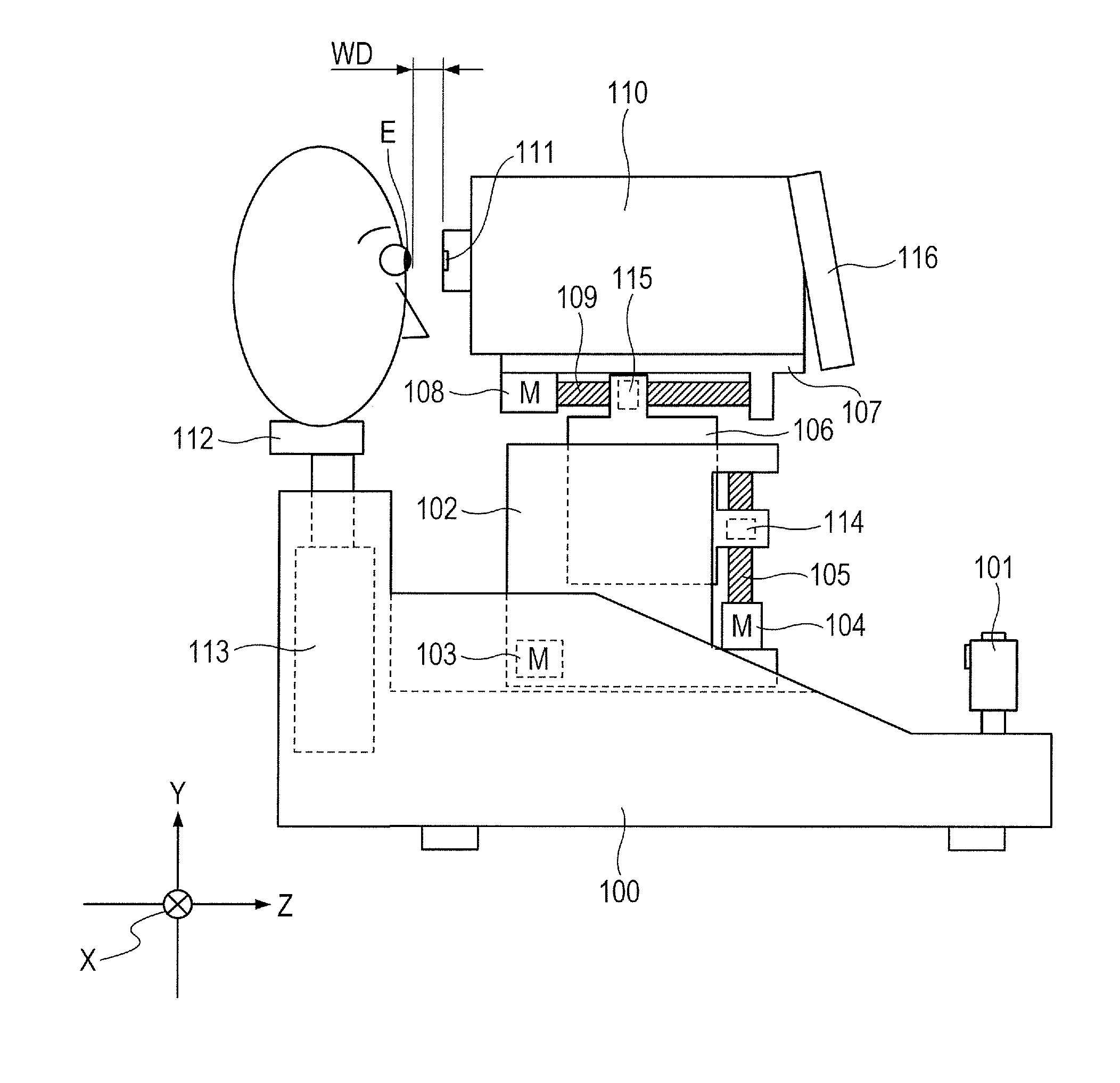
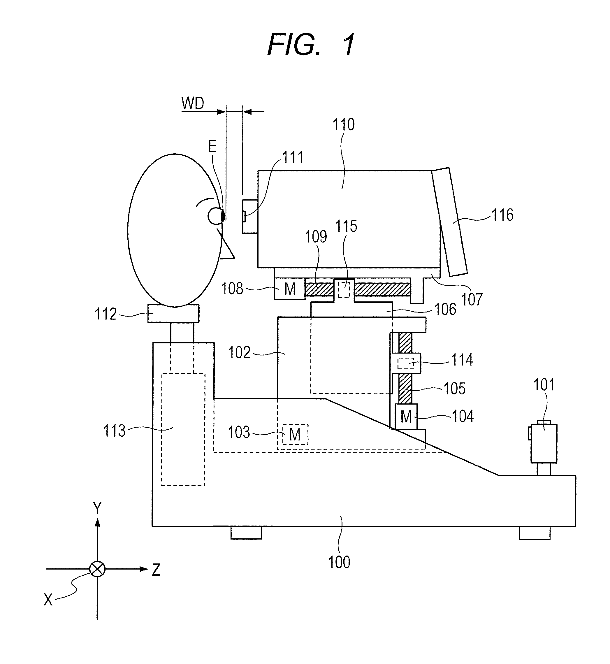
[0035]FIG. 1 is a view showing the schematic arrangement of a non-contact tonometer according to the present invention.

[0036]A frame 102 is movable in the left-and-right direction (to be referred to as an X axis direction hereinafter) with respect to a base 100. A drive system in the X axis direction is constituted by an X axis drive motor 103 fixed on the base 100, a feed screw (not shown) coupled to a motor output axis, and a nut (not shown) fixed to the frame 102 so as to be movable on the feed screw in the X axis direction. The motor 103 rotates to move the frame 102 in the X axis direction via the feed screw and nut.

[0037]A frame 106 is movable in the up-and-down direction (to be referred to as a Y axis direction hereinafter) with respect to the frame 102. A drive system in the Y axis direction is constituted by a Y axis drive motor 104 fixed on the frame 102, a feed screw 105 coupled to a motor output axis, and a nut 114 fixed to the frame 106 so as to be movable on the feed s...

second embodiment

[0091]FIG. 11 is a view showing the outer appearance of a cylinder portion according to the second embodiment of the present invention. As in the first embodiment, a plurality of air vent holes Ap1 to Ap4 are formed in the outer wall of a cylinder 43. Electromagnetic valves 50 to 53, and stoppers 54 to 57 are arranged outside the cylinder 43 in correspondence with the respective air vent holes Ap1 to Ap4. The electromagnetic valves 50 to 53 can be independently driven. By driving the electromagnetic valves 50 to 53, the stoppers 54 to 57 can close the air vent holes Ap1 to Ap4. FIGS. 12A to 12D are views for explaining the operation of the cylinder portion in the embodiment. The air vent hole Ap4 is selected in FIG. 12A, the air vent hole Ap3 is selected in FIG. 12B, the air vent hole Ap2 is selected in FIG. 12C, and the air vent hole Ap1 is selected in FIG. 12D. When each air vent hole is selected, it is controlled to close an air vent hole arranged on the side of an eye to be insp...

third embodiment

[0094]FIG. 13 is a view showing the outer appearance of a cylinder portion according to the third embodiment of the present invention. FIGS. 14A to 14D are views for explaining the operation of a cylinder portion in the third embodiment. As shown in FIG. 14A, an elongated air vent hole Ap1 is formed in the outer wall of a cylinder 58. A rotation member 59 for changing the air vent hole position is arranged outside the cylinder 58. An elongated hole is formed at an angle in the outer wall of the rotation member 59 so that it crosses the elongated hole of the cylinder 58. A leakage preventing member 60 is arranged at the intersection between the elongated air vent hole Ap1 of the cylinder 58 and the elongated hole of the rotation member 59 to prevent leakage of air from the groove of the elongated hole of the cylinder 58. Further, a drive gear 47 fitted on the output shaft of a drive motor 48 is arranged to mesh with the gear shape of the flange portion of the rotation member 59. The ...


PUM


Abstract

In a non-contact tonometer, puffing of air unnecessary for measurement of an eye to be inspected after driving of a solenoid is stopped is suppressed. In the non-contact tonometer including a corneal shape change unit configured to change the shape of the cornea by pressurizing and supplying a gas in a cylinder by a piston, and an eye pressure measuring unit configured to measure the eye pressure from the state of the shape change of the cornea, an opening portion configured to be formed in the outer wall of the cylinder and decide the internal volume of the cylinder when pressurizing the gas, and a pressurized gas volume change unit configured to change a position where the opening portion can connect the inside of the cylinder with the outside, and change the internal volume of the cylinder when pressurizing the gas.

Description

BACKGROUND OF THE INVENTION[0001]1. Field of the Invention[0002]The present invention relates to a non-contact tonometer which computes an eye pressure value from a corneal shape change signal obtained by an optical detection means upon puffing air against an eye to be inspected to change the corneal shape.[0003]2. Description of the Related Art[0004]A non-contact tonometer is typified by an air puff tonometer developed by Bernard Grolman. This tonometer optically detects the applanation of the cornea by puffing air against the cornea of an eye to be inspected from a nozzle about 11 mm apart from the cornea. Then, the time till the applanation is calibrated by a contact Goldmann tonometer, computing an eye pressure value.[0005]Most tonometers of this type use a system in which a piston moves inside a cylinder connected to an air puff nozzle portion to pressurize air in the cylinder and puff the air from the nozzle. As the piston drive system, a solenoid is generally used because of ...

Claims


Application Information

Patent Timeline
Patent Type & Authority Applications(United States)
IPC IPC(8): A61B3/16
CPCA61B3/165
Inventor AKIBA, SHINTARODOBASHI, YASUHIRO
Owner CANON KK
Why Eureka
Try Eureka