

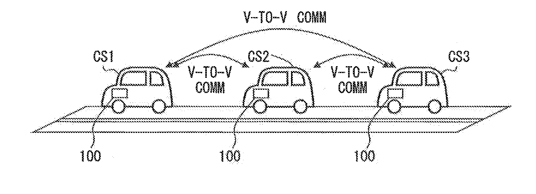
Platoon travel system
a technology for traveling systems and platoons, applied in braking systems, process and machine control, instruments, etc., can solve the problems of increasing wasting and consuming more travel energy of the low travel output vehicle. , to achieve the effect of preventing the deterioration of the energy consumption of the whole platoon
- Summary
- Abstract
- Description
- Claims
- Application Information
AI Technical Summary
Benefits of technology
Problems solved by technology
Method used
Image

Examples
modification example 1
[0251]The above-mentioned embodiment uses two types of vehicles as an example of vehicle group classification for the explanation of the platoon. However, the present disclosure is not limited to such configuration. That is, as shown in FIG. 16, three types of vehicles may also be used for organizing a platoon.
[0252]The configuration of the platoon travel system in the modification example 1 is the same as the one in the above-mentioned embodiment. Further, most of the processing operations of the platoon travel system in the modification example 1 are the same as the processing operation in the above-mentioned embodiment. Here, description is focused to the difference of the processing operation of the platoon travel system in the modification example 1 from the one in the above-mentioned embodiment.
[0253]In FIG. 16, the platoon includes, in addition to the first vehicle group and the second vehicle group, the third vehicle group that is a group of medium-size vehicles. In this cas...
modification example 2
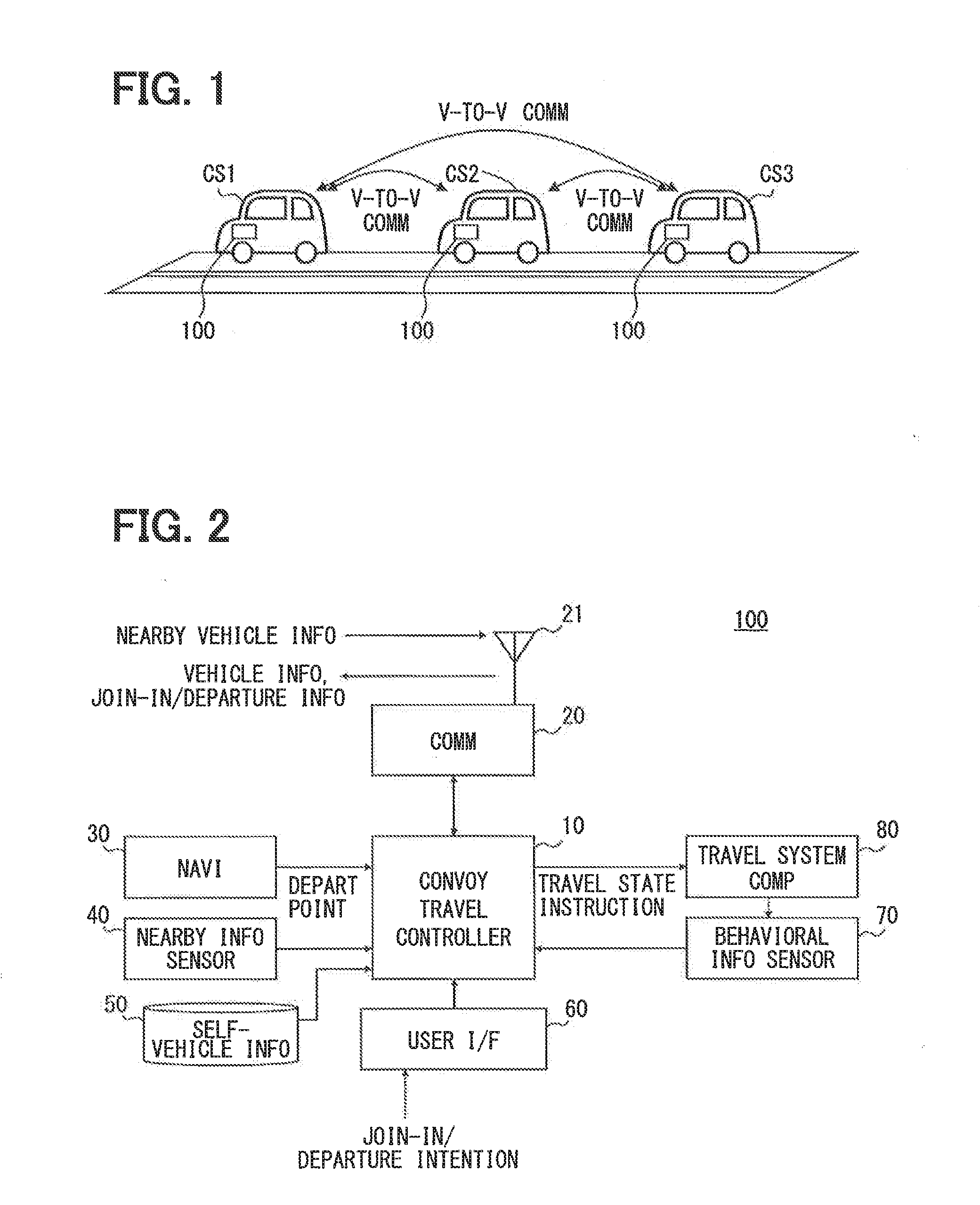
[0270]When having a joining vehicle joining into the platoon or having a departing vehicle departing from the platoon, the platoon travel system may perform speed reduction control by using deceleration plan information which shows a deceleration plan for decelerating the decel-target vehicle(s), for the adjustment of the inter-vehicle distance. In the modification example 2, the platoon travel system uses such a deceleration plan. Further, in the modification example 2, the nearby information sensor 40, which detects existence of a vehicle in front of the self-vehicle as well as an inter-vehicle distance to a front vehicle, is adopted. In other words, the ECU 10 in each of the platoon vehicles acquires the inter-vehicle distance to the front vehicle from the nearby information sensor 40 (i.e., a first acquisition unit in the claims). That is, each of the platoon vehicles monitors a front of the self-vehicle. In the modification example 2, like parts have like numbers as the above e...
modification example 3
[0299]The nearby information sensor 40 may be a sensor that is capable of detecting existence of a vehicle behind the self-vehicle as well as an inter-vehicle distance to a behind vehicle. In the modification example 3, the platoon travel system is configured to use the deceleration plan information, while adopting the nearby information sensor 40 which detects existence of a vehicle behind the self-vehicle as well as an inter-vehicle distance to a behind vehicle. In other words, the ECU 10 in each of the platoon vehicles acquires the inter-vehicle distance to a behind vehicle from the nearby information sensor 40 (i.e., a second acquisition unit in the claims). That is, the platoon vehicles respectively monitor a back of the self-vehicle. In the modification example 3, like parts have like numbers as the above embodiment and modification, and description of the like parts is not repeated for the brevity of explanation. Further, the deceleration plan information is created in the sa...
PUM
 Abstract
Description
Claims
Application Information