Road illumination system

a road illumination and road technology, applied in the field of saving illumination energy, can solve the problems of complex systems, considerable traffic hazards, and many roads not lighted, and achieve the effect of saving energy and saving illumination energy

Inactive Publication Date: 2014-10-30
ASSOULIN DANIEL
View PDF4 Cites 35 Cited by
  • Summary
  • Abstract
  • Description
  • Claims
  • Application Information

AI Technical Summary

Benefits of technology

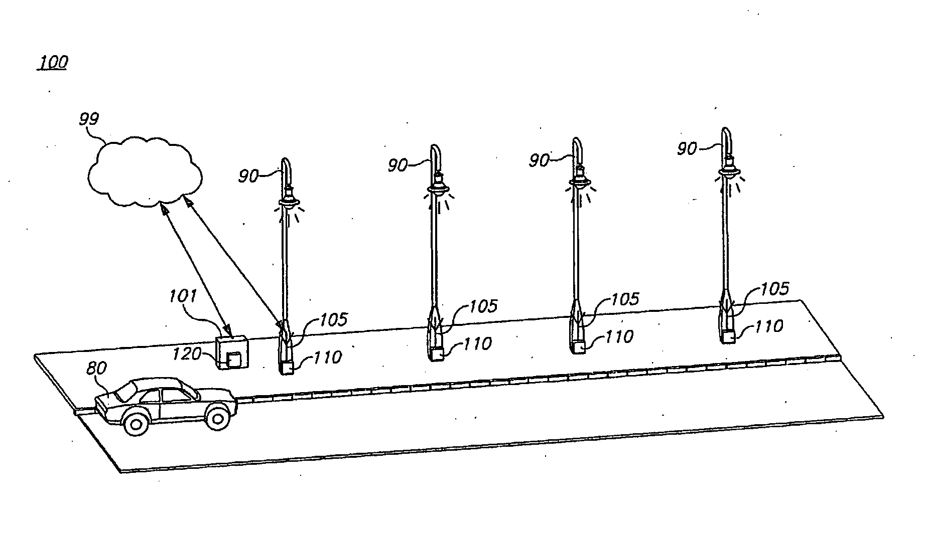
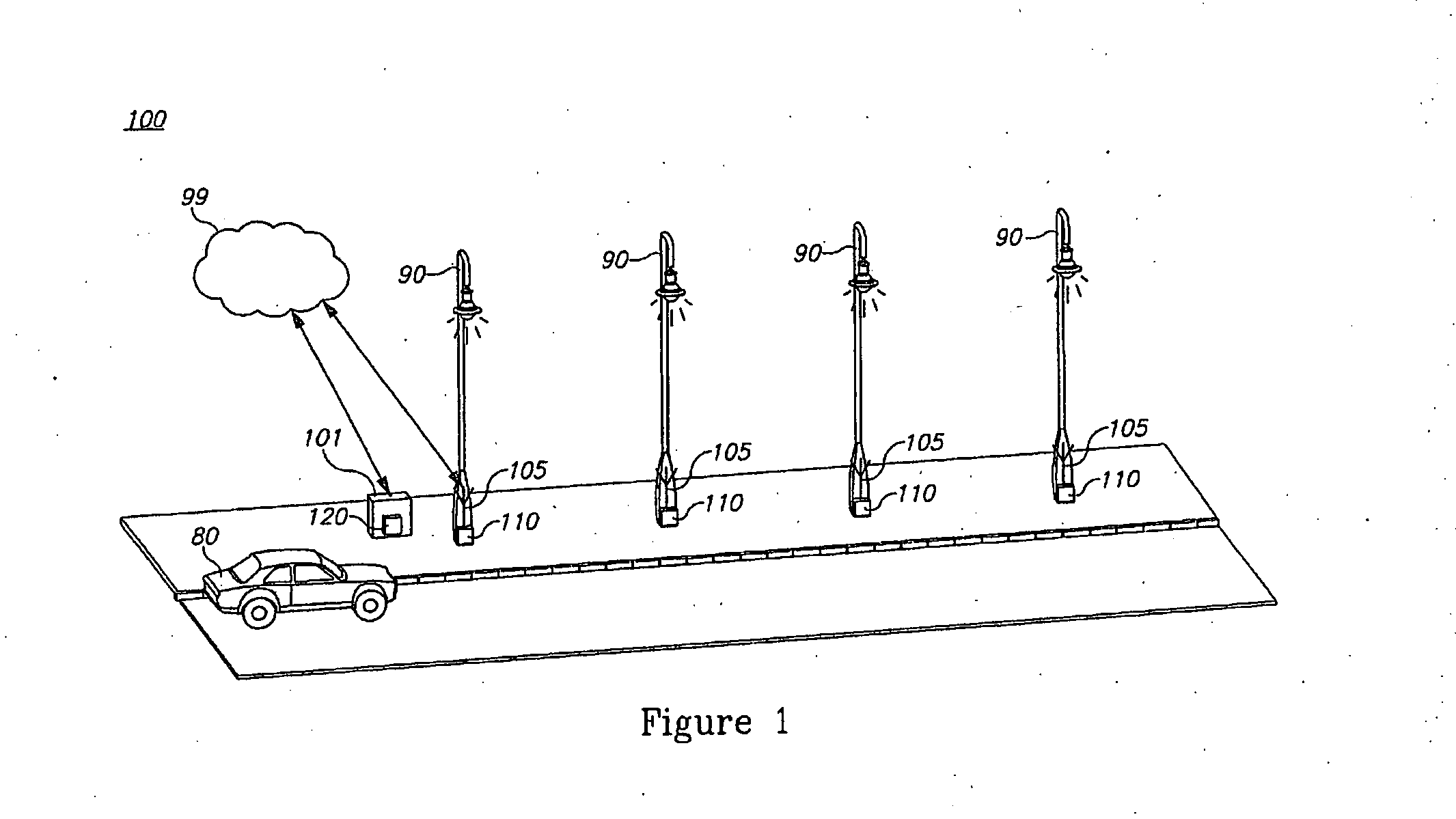
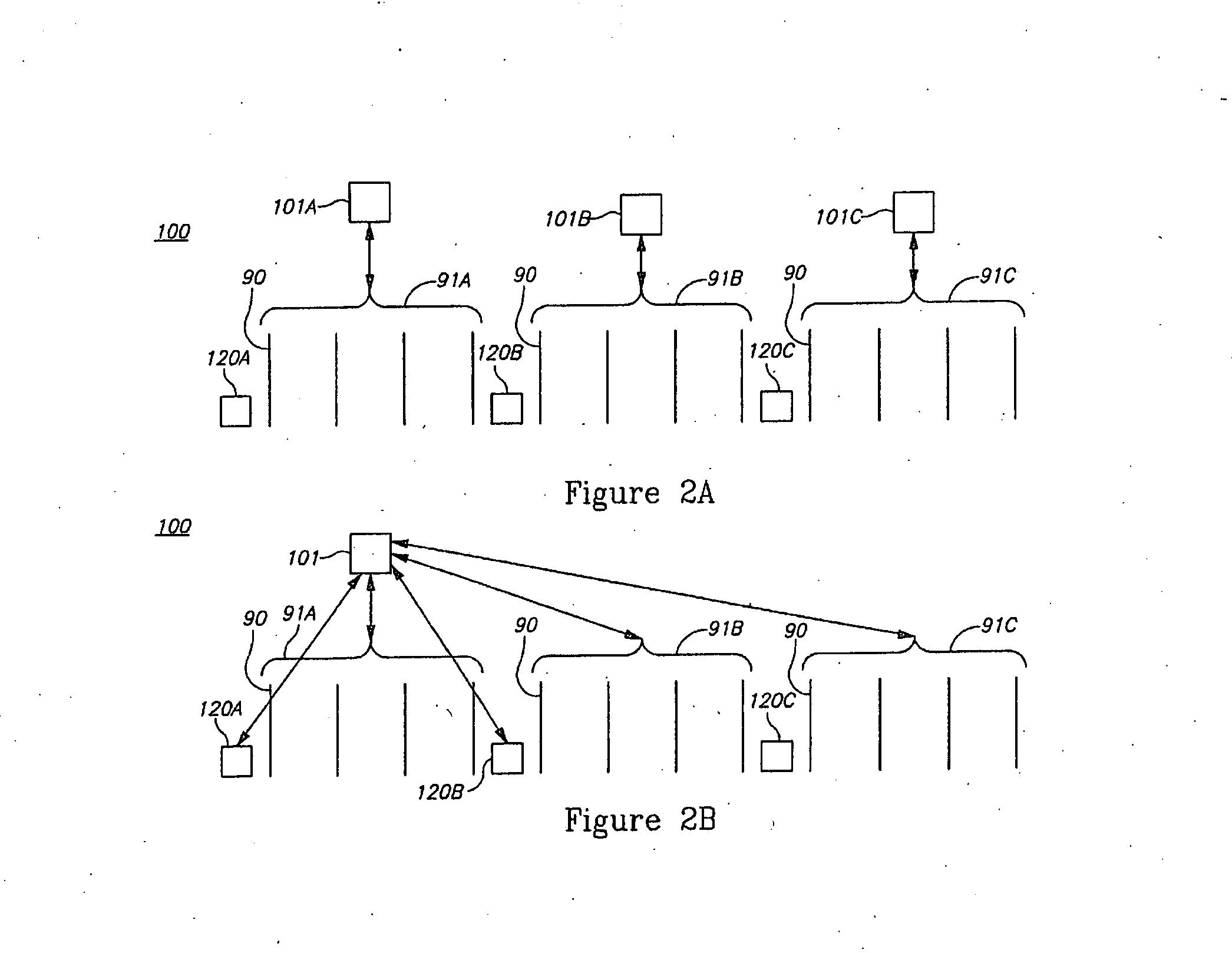
[0005]One aspect of the present invention provides a road illumination system comprising: at least one sensor arranged to detect an approaching vehicle on a road, a plurality of switches, each associated with a street light and arranged to switch the street light on and off, a controller arranged to receive a vehicle detection from the at least one sensor and activate, via a communication link, switches associated with a specified group of street lights for a specified period, wherein an activation speed is higher than a maximal vehicle speed, wherein the specified group comprises at least the street lights within a shorter distance between one kilometer ahead of the vehicle, and a distance between the vehicle and the vehicle's horizon; and the specified period is at least an estimated travelling period across the specified group of street lights, wherein the switch is arranged to switch the associated street light off after a specified period in which no activation signal is received from the controller, and wherein each switch is further arranged to switch the associated street light constantly on upon detection of malfunctioning of the communication link.

Problems solved by technology

Many roads are not lighted because of high price of electricity and too thin traffic that make it unworthy.
Prior art documents, such as GB 2,444,734, GB 2,455,504, BE 1,009,084, EP 2,271,184, JP 6,096,865 and US 2010 / 148,696 disclose various systems that aim at saving illumination energy along streets, but these systems are elaborate, expensive and sensitive to failures which may result in considerable traffic hazards.

Method used


Image

  • Road illumination system
  • Road illumination system
  • Road illumination system

Examples


Embodiment Construction

[0010]With specific reference now to the drawings in detail, it is stressed that the particulars shown are by way of example and for purposes of illustrative discussion of the preferred embodiments of the present invention only, and are presented in the cause of providing what is believed to be the most useful and readily understood description of the principles and conceptual aspects of the invention. In this regard, no attempt is made to show structural details of the invention in more detail than is necessary for a fundamental understanding of the invention, the description taken with the drawings making apparent to those skilled in the art how the several forms of the invention may be embodied in practice.

[0011]Before explaining at least one embodiment of the invention in detail, it is to be understood that the invention is not limited in its application to the details of construction and the arrangement of the components set forth in the following description or illustrated in ...


PUM


Abstract

A road illumination system having sensors detecting approaching vehicles and operating thereupon and via a controller switches associated with street lights is provided herein. The system turns street lights off when no vehicles are present and spares thereby electricity. The system activates the street lights groupwise, to supply enough illumination with a minimal amount and complexity of equipment. The system further has an extended ability to identify malfunctioning and exceptional situations, in which is activates the street lights continuously. The system is a distributed wireless one, and may be configured remotely.

Description

BACKGROUND[0001]1. Technical Field The present invention relates to the field of energy saving, and more particularly, to saving illumination energy.[0002]2. Discussion of Related Art[0003]Many street lamps are activated at dark time all night long. Many roads are not lighted because of high price of electricity and too thin traffic that make it unworthy.[0004]Prior art documents, such as GB 2,444,734, GB 2,455,504, BE 1,009,084, EP 2,271,184, JP 6,096,865 and US 2010 / 148,696 disclose various systems that aim at saving illumination energy along streets, but these systems are elaborate, expensive and sensitive to failures which may result in considerable traffic hazards.BRIEF SUMMARY[0005]One aspect of the present invention provides a road illumination system comprising: at least one sensor arranged to detect an approaching vehicle on a road, a plurality of switches, each associated with a street light and arranged to switch the street light on and off, a controller arranged to recei...

Claims


Application Information

Patent Timeline
Patent Type & Authority Applications(United States)
IPC IPC(8): H05B33/08H05B37/02H05B44/00
CPCH05B37/02H05B33/0842G08G1/052F21S2/00F21S8/086F21V23/0471F21W2131/103F21Y2115/10H05B47/19H05B47/115H05B45/00Y02B20/40F21S8/00F21S8/08H05B47/105
Inventor ASSOULIN, DANIEL
Owner ASSOULIN DANIEL
Why Eureka
Try Eureka