

Method for considerably enhancing the availability of wireless connections
- Summary
- Abstract
- Description
- Claims
- Application Information
AI Technical Summary
Benefits of technology
Problems solved by technology
Method used
Image

Examples
first embodiment
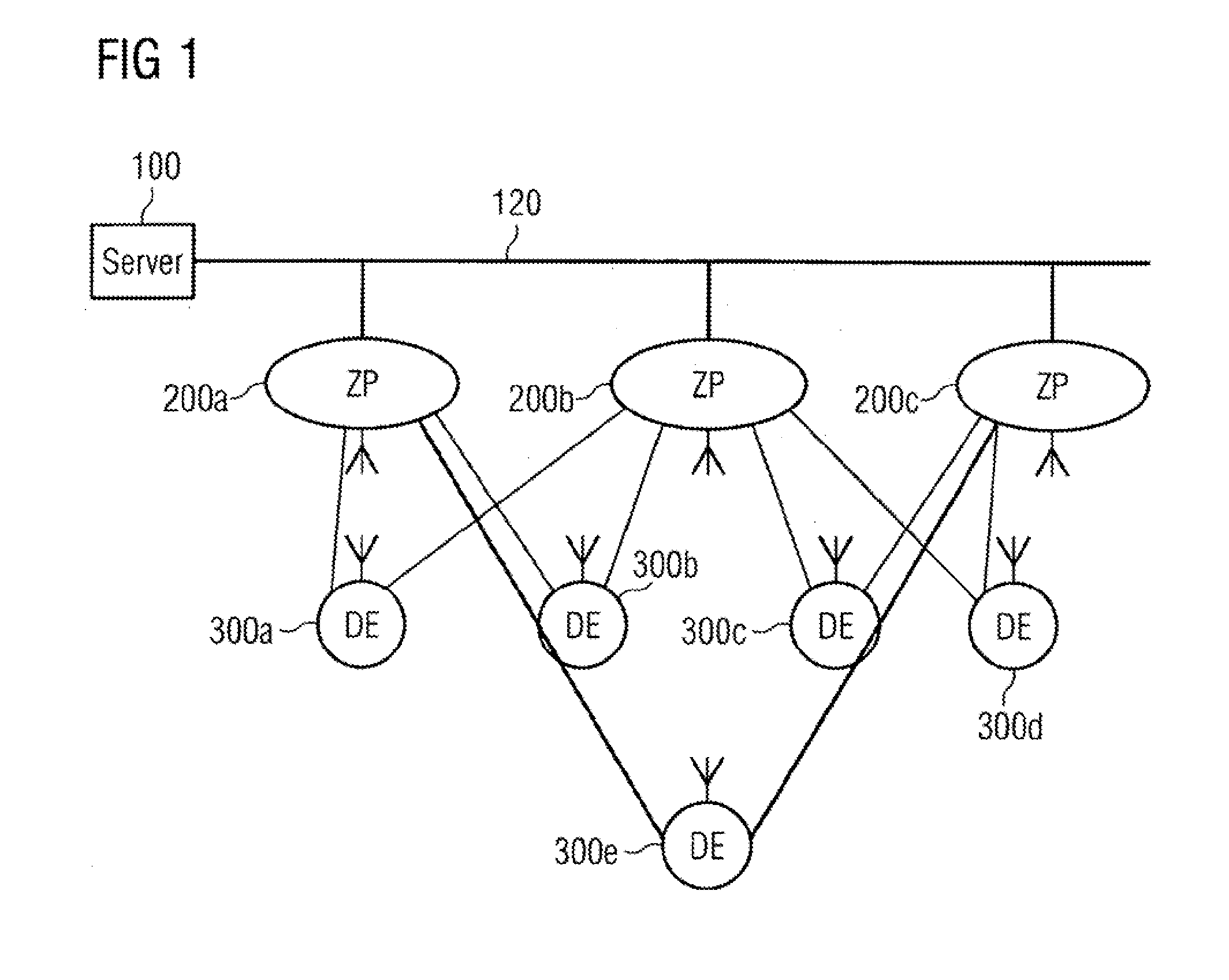
[0054]a method for controlling (coordinating) the wireless data transmission in the uplink direction is shown in FIG. 4. If a message (one and the same message) is transmitted by a wireless terminal 300b in the uplink direction to the access point 200a as well as to the access point 200b, then both of these access points 200a, 200b receive the message via their respective assigned communications channels to the wireless terminal in step 402. It is possible for one or both of the communications channels from the wireless terminal to the access points to be free of interference and, correspondingly, for one or both of the access points to correctly receive the message. However, it is also possible for errors to occur in the transmission and for one or both access points 200a, 200b to receive faulty messages. It is moreover possible for both transmission channels from the wireless terminal 300b to the access points 200a, 200b to experience interferences of different strengths, i.e., fo...
second embodiment
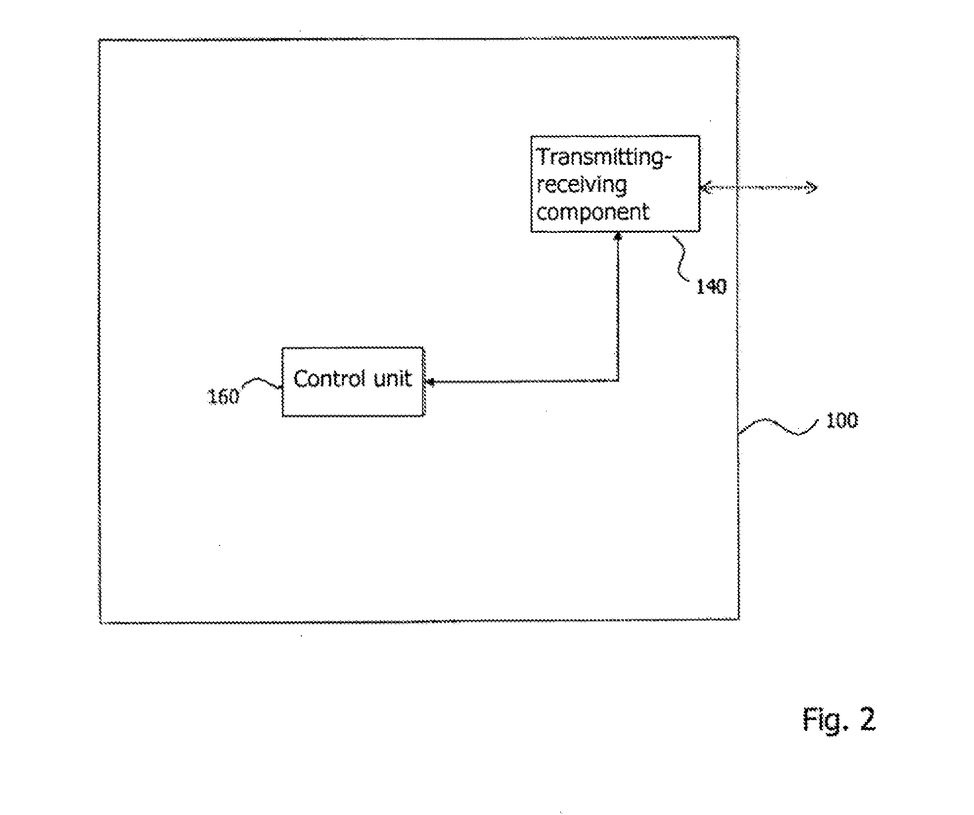
[0056]a method for controlling the data transmission in the uplink direction is shown in FIG. 5. According to this embodiment, the wireless terminal 300b transmits a message in the uplink direction respectively via a communications channel to the access point 200a and to the access point 200b. The messages received by the access points 200a, 200b in step 502 are combined by the control unit 160 according to a second metric (step 504) independently of whether the control unit 160 is located in the server 100 or disposed in a decentralized fashion between the access points 200a, 200b. The combination of the received messages then indicates the correct message with a high degree of probability or, in particular, precisely.
[0057]FIGS. 6a and 6b each show the same section of the communications network from FIG. 1 with the server 100, the data bus 120, the two access points 200a, 200b, and the wireless terminal 300b assigned to the two access points 200a, 200b. As an alternative to being ...
third embodiment
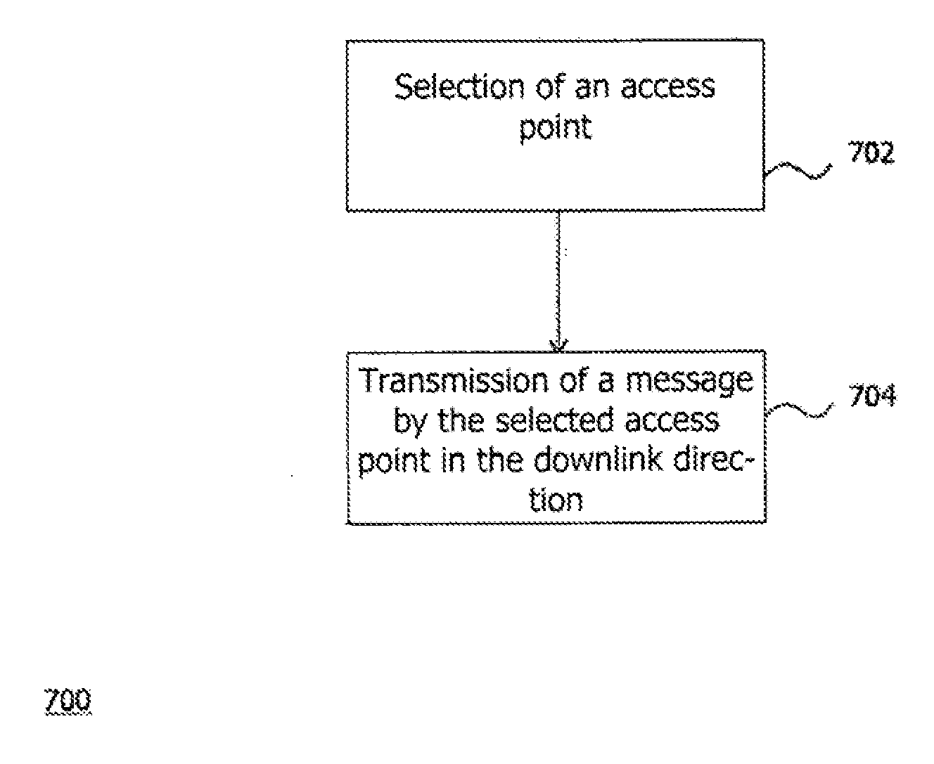
[0058]FIG. 7 schematically shows a flowchart of the method for data transmission in the downlink direction.
[0059]For example, the server 100 wishes to transmit a message to the wireless terminal 300b. Alternatively, another wireless terminal wishes to transmit data to the wireless terminal 300b via the server 100. Independently of whether the original message originates from the server 100 or from another wireless terminal, the message is conducted from the server to the access point 200a and the access point 200b via the data bus 120 in a wired fashion. In step 702, the decision is then made as to which of the access points 200a, 200b should transmit the message to the wireless terminal 300b in a wireless fashion. The selection may, for example, be performed at random.
[0060]According to the embodiment assumed by way of example, however, the selection is not made at random, but rather takes into account information regarding the respective transmission channel between the two acces...
PUM
 Abstract
Description
Claims
Application Information