[0010]An objective of embodiments of the present invention is to provide a dust repellent, a tool insert part, a tool mount, and a
machine tool by which the restriking of a tool can at least be reduced. In particular, a dust repellent, a tool insert part, a tool mount, and / or a
machine tool may be embodied such that they develop suitable braking effects in reference to a tool, so that a restriking of the tool is at least reduced. In particular, a braking effect may be created upon the tool during the completion of a
processing procedure, particularly when lifting the
machine tool after the
processing procedure.
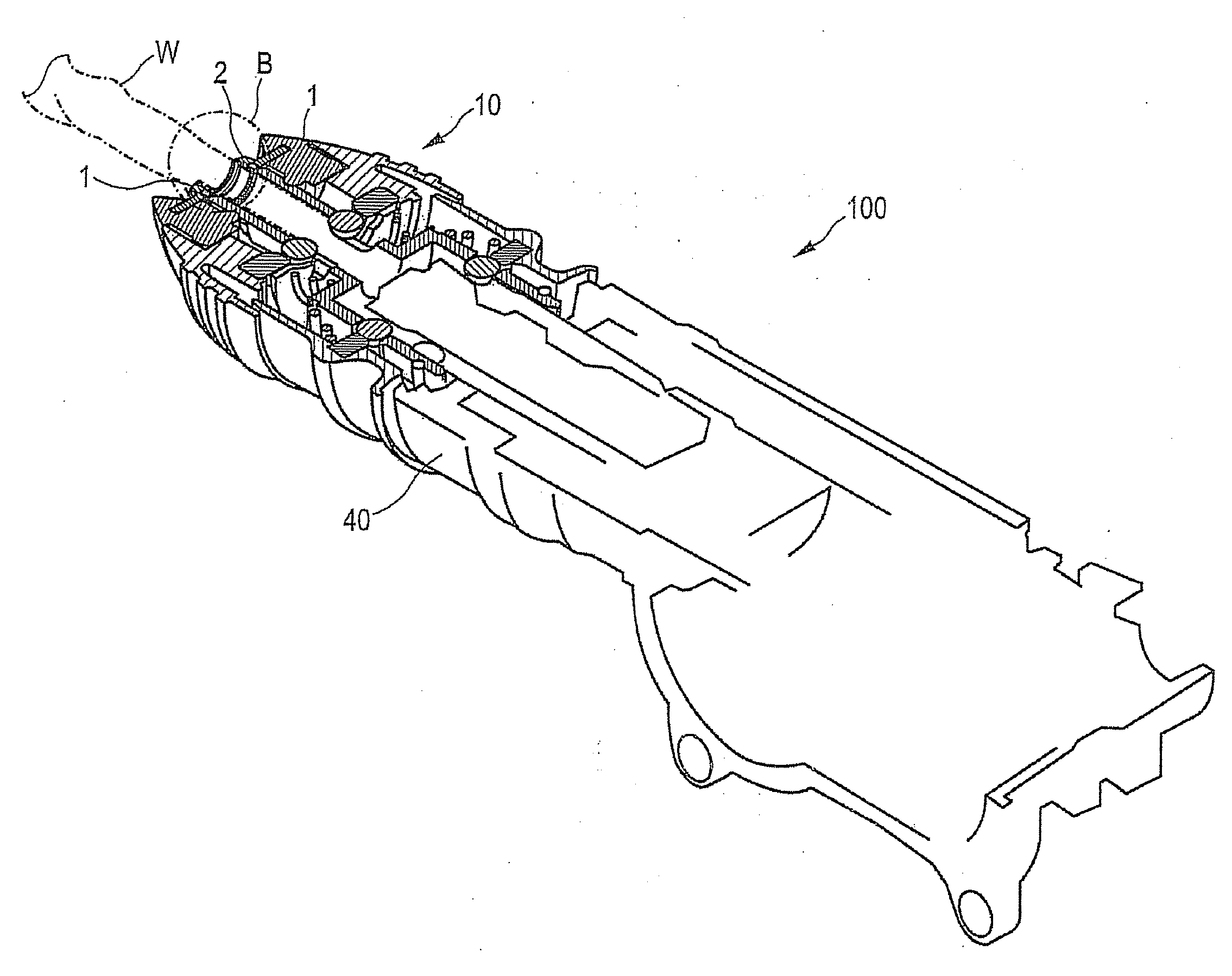
[0014]Aspects of the present invention are based on the idea that at the end of a
processing procedure, i.e. particularly when lifting the
machine tool with the tool off the underground to be processed, the tool should be held in a frontal position. Holding the tool in its frontal position regularly prevents the restriking of the tool. This allows for the prevention of the hammer mechanism's reaching a new operating site and being reactivated due to a rebounding tool.
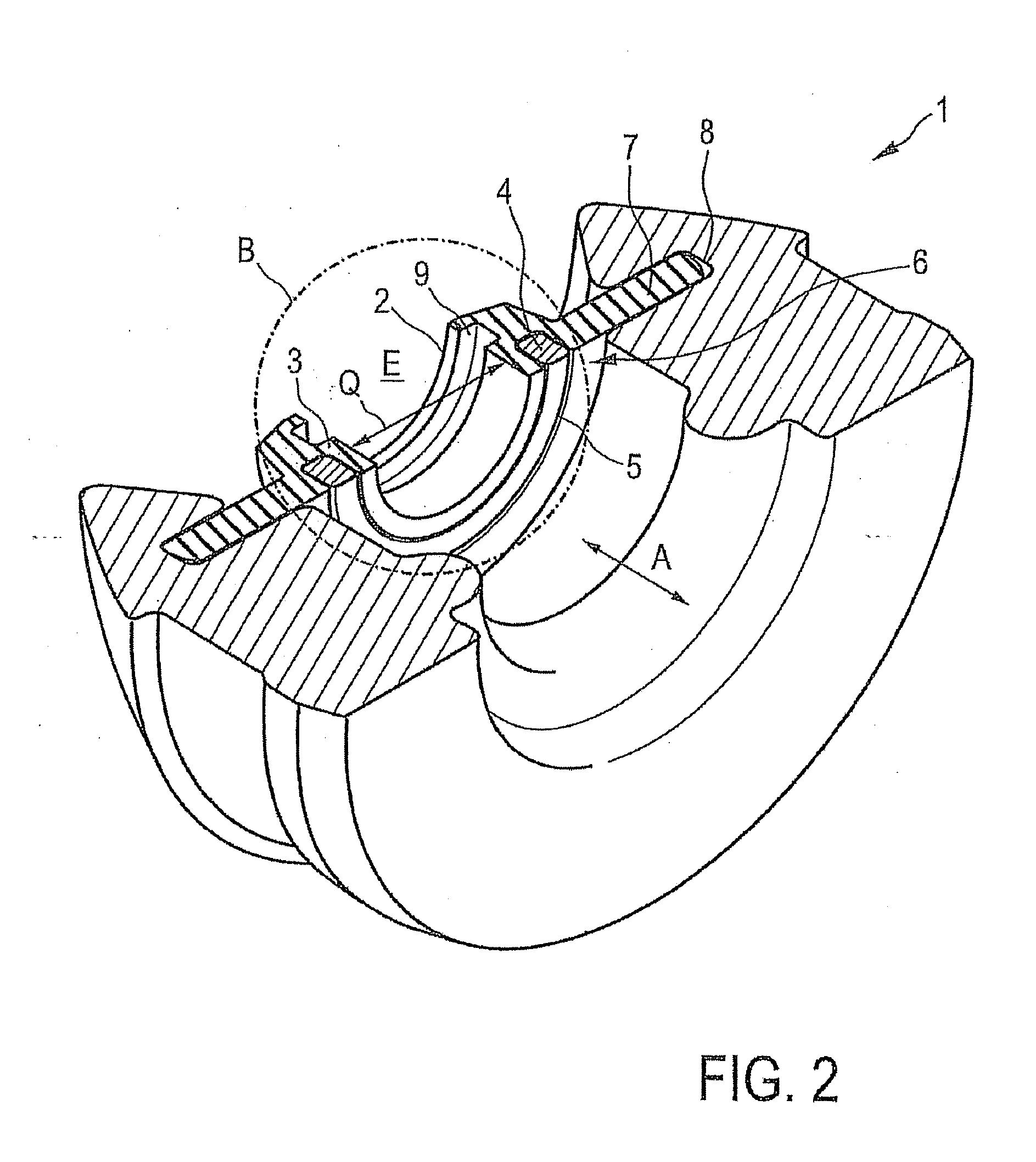
[0019]A particular
advantage of embodiments of the present invention is that the insert ring, on the one hand, and at least the annular section of the annular cap, on the other hand, show an expansion behavior under the influence of heat such that a cross-section of the insert opening is smaller under the influence of heat than without the influence of heat. Advantageously, during the processing procedure—i.e. through a hammering or striking motion of the tool, potentially also by a rotary motion of the tool—heat is created at the annular section, which under the influence of the insert ring serves to reduce the cross-section of the insert opening. This results in an increased
friction effect upon a tool, which can hold said tool effectively in its frontal position, but in any case also brakes it. The
friction effect is sufficient to hold the tool in its frontal position in a friction-fitting manner or to brake a tool that is striking back to such an extent that it does not undesirably activate the hammer mechanism. Overall it has been shown that a cross-section of the insert opening under the influence of heat, i.e. usually after the end of the processing procedure, is smaller compared to a situation without the influence of heat. Under the influence of heat, a tool can be held directly or indirectly at the annular section of the annular cap in a friction-fitting fashion. In general, it is preferable that the annular section of the annular cap directly limit the insert opening. However, it is also possible for the annular section of the annular cap to limit the insert opening only indirectly—for example, by encompassing another annular part—preferably increasing the
friction effect.
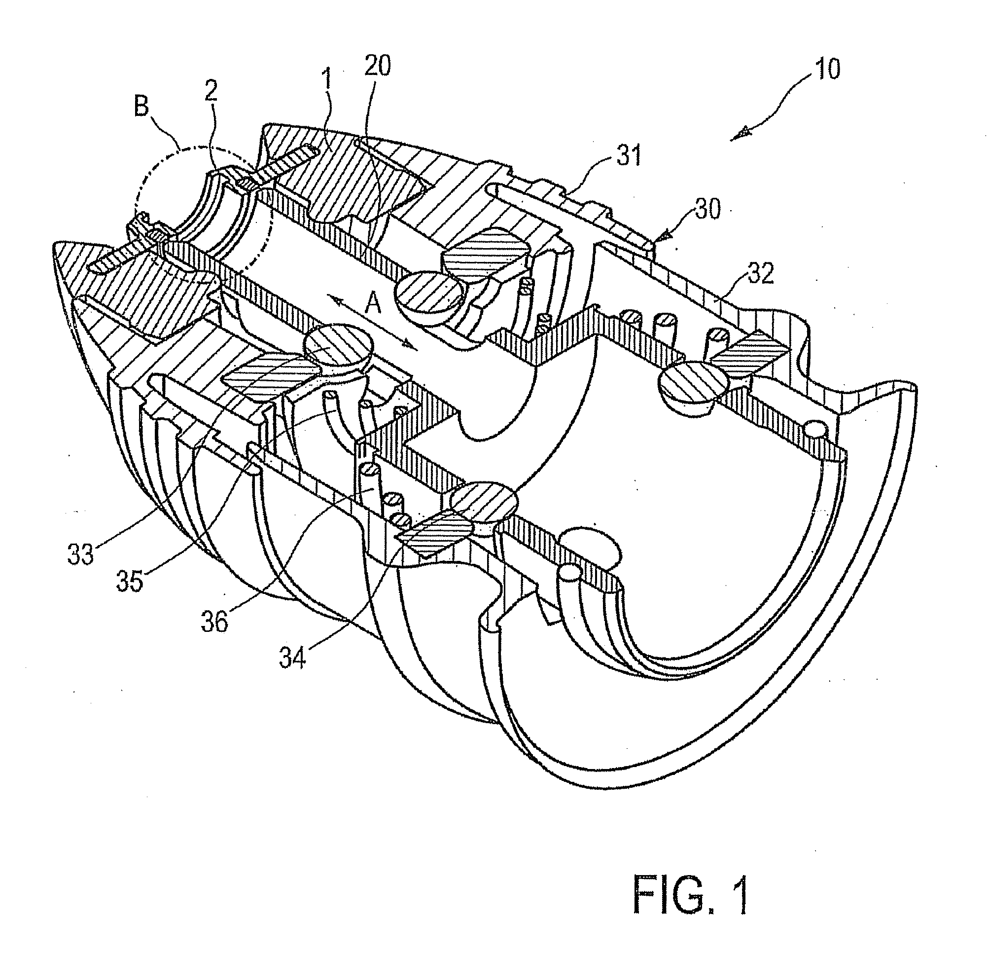
[0021]Within the scope of a particularly preferred further embodiment the annular cap provides a groove at the side of the tool, open for an axial mount. It serves to improve the dust-repelling effect of the tool brake. The annular section is preferably arranged in the axial direction at the machine side of the open groove. Therefore, the tool insert part offers a sufficiently large friction-fitting holding surface for the tool.
[0022]The annular cap preferably comprises an annular
flange, held in an insert groove of the tool insert part. This way, the annular cap can be mounted to the tool insert part in a particularly secure fashion. The insert ring is arranged in a particularly preferred fashion axially at the height of the annular
flange. The insert ring, aligned this way radially between the annular section and the annular
flange, is arranged particularly securely in the tool insert part and increases at this point the effect of aspects of the concept of the invention. An insert groove of the tool insert part is preferably arranged in a surface of the annular cap facing a machine tool. The insert ring is thus protected from external influences and additionally, in combination with the annular section, particularly under the influence of heat, it can develop a particularly strong friction-fitting holding effect upon a tool after a processing procedure has ended.

