
Networked anemometer system for windmeasurement

a networked anemometer and wind measurement technology, applied in the field of methods and systems for measuring wind with networked anemometers, can solve problems such as inability to adjust to weather conditions, increase the risk of errors in manual observations, and introduce inability to adjust calculations

Active Publication Date: 2014-10-30
TORREY PINES LOGIC
View PDF1 Cites 24 Cited by
  • Summary
  • Abstract
  • Description
  • Claims
  • Application Information

AI Technical Summary

Benefits of technology

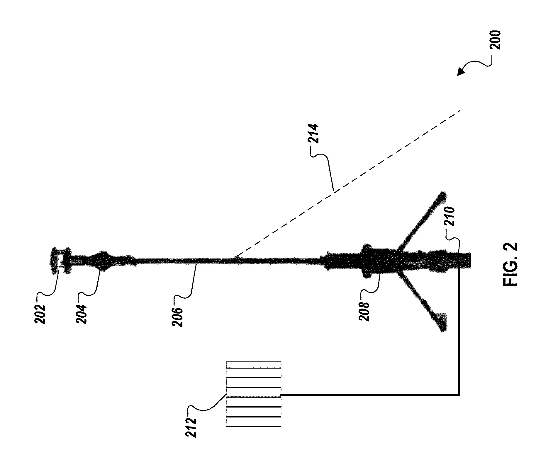
The patent describes a networkable anemometer sensor platform that can measure wind and other weather conditions. This platform is portable, easily deployed, and can be used in a networked anemometer system. It can provide accurate measurements of wind speed and direction, which can enhance the efficiency of various applications such as wind turbines, pesticide dispersal, and irrigation. The data collected by the platform can also help in improving training and safety for weapon operators and assistant target spotters. Overall, this technology allows for real-time, high-accuracy measurements of wind speed and direction, which can be useful in various applications.

Problems solved by technology

Wind can be unpredictable and influence, among other things, the behavior, performance, and movement of objects.
At higher observational ranges, manual observations become more error prone.
To accurately determine cumulative wind effects, a single measurement point is not sufficient and reliance upon a single measurement can introduce unacceptable error into calculations for mitigating wind effects for longer-range-dependent activities.

Method used


Image

  • Networked anemometer system for windmeasurement
  • Networked anemometer system for windmeasurement
  • Networked anemometer system for windmeasurement

Examples


Embodiment Construction

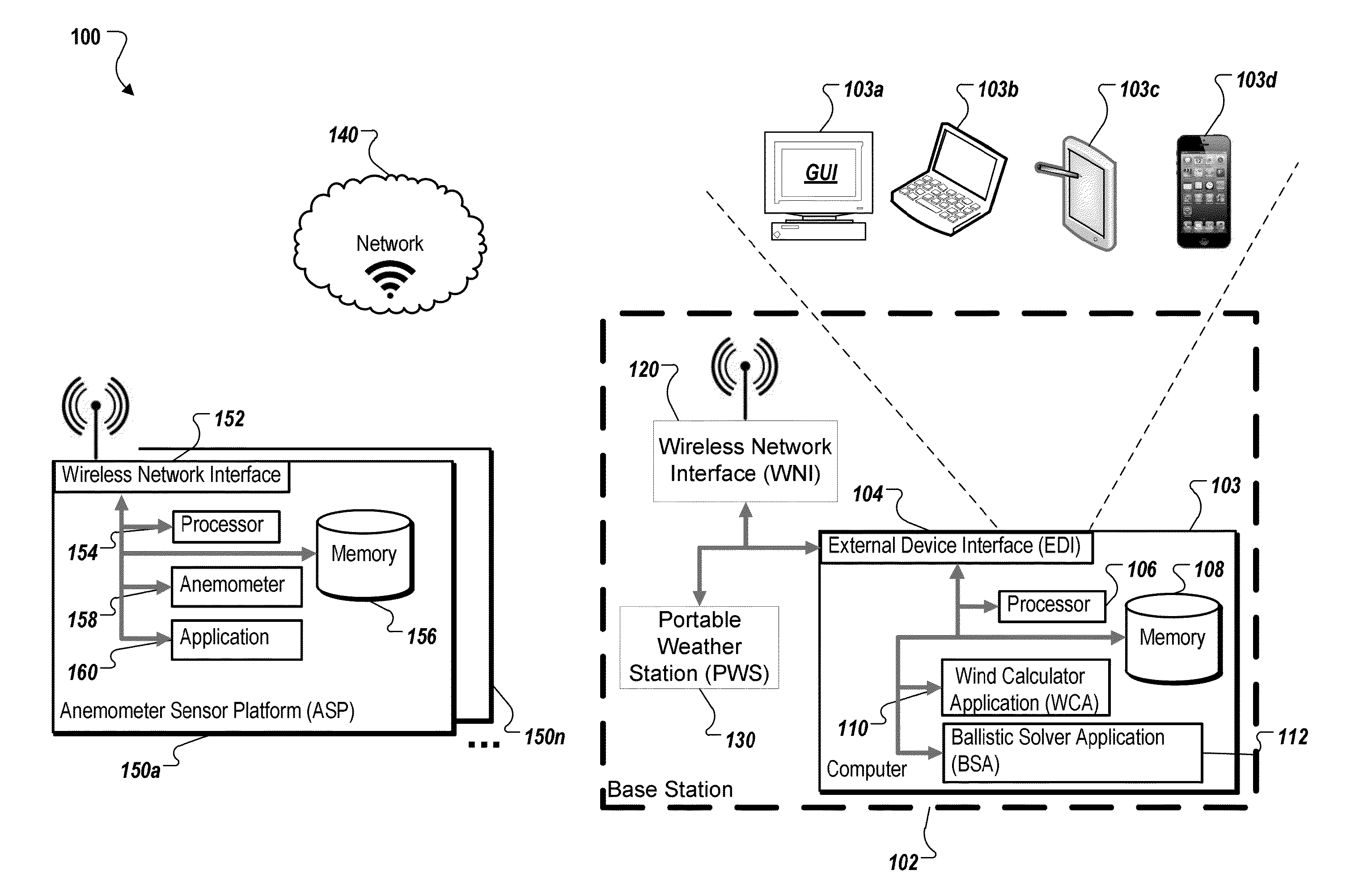
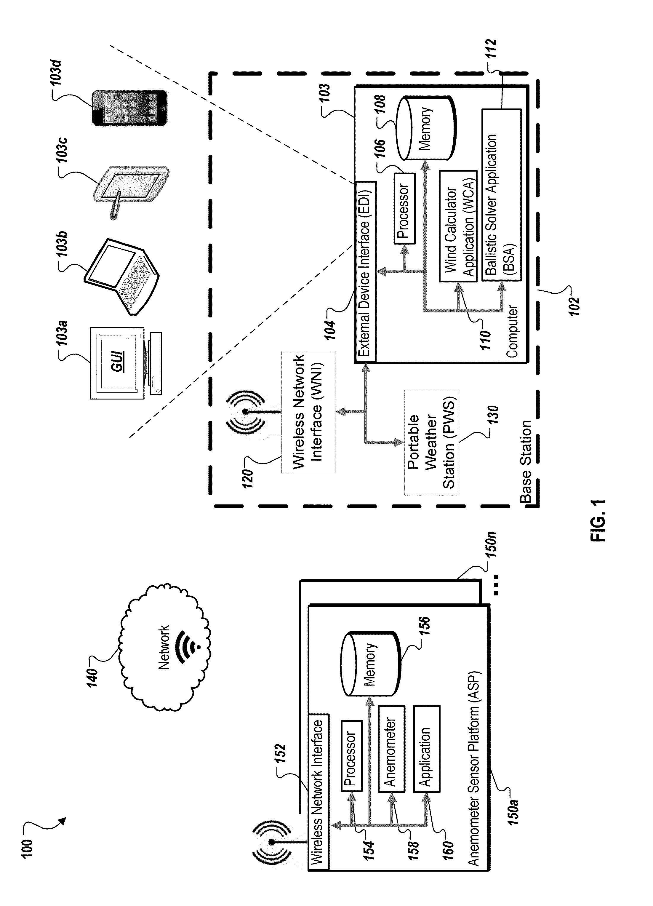
[0026]This disclosure generally describes methods and systems for measuring wind with networked anemometers.

[0027]The following description is presented to enable any person skilled in the art to make and use the invention, and is provided in the context of a particular application and its requirements. By measuring wind components at different ranges from an origin, using networked anemometers, a cumulative wind profile can be calculated. The calculated cumulative wind profile can be used in various applications to mitigate (or “offset”) one or more effects of measured wind components. For example, to offset range wind and / or crosswind effects on a projectile, one or more aiming / sighting offset values can be calculated using the cumulative calculated wind profile. Various modifications to the disclosed implementations will be readily apparent to those skilled in the art, and the general principles defined herein may be applied to other embodiments and applications without departing...


PUM


Abstract

The present disclosure describes structures, methods, and functionality for measuring a wind profile with networked anemometers. One method includes receiving real-time wind measurement data from each of one or more anemometer sensor platforms (ASPs) in a network, receiving atmospheric data, and calculating, using the received real-time wind measurement data and the received atmospheric data, at least one of real-time wind measurements, a wind profile, an average wind speed, or a weapon aiming offset.

Description

[0001]This application is related to co-pending U.S. patent application Ser. No. ______, filed on ______. The entire contents of co-pending U.S. patent application Ser. No. ______ are hereby incorporated by reference.BACKGROUND[0002]Wind can be unpredictable and influence, among other things, the behavior, performance, and movement of objects. Wind measurements are often estimated for a particular location by manual, visual observations. Estimation accuracy can be dependent upon observer training, experience, skill, available observation equipment, atmospheric conditions, and observational range. At higher observational ranges, manual observations become more error prone. To accurately determine cumulative wind effects, a single measurement point is not sufficient and reliance upon a single measurement can introduce unacceptable error into calculations for mitigating wind effects for longer-range-dependent activities.SUMMARY[0003]The present disclosure relates to methods and systems...

Claims


Application Information

Patent Timeline
IPC IPC(8): G01W1/00G01W1/02
CPCG01W1/02G01W1/00Y02A90/10F41G3/08G01S19/13G01W1/06
Inventor VOLFSON, LEO
Owner TORREY PINES LOGIC
Learn More