Dual-fuel gas-pellet burner assembly

a gas-pellet burner and dual-fuel technology, applied in the direction of household stoves or ranges, solid heating fuel, lighting and heating equipment, etc., can solve the problems of limited heat generated for larger cooking areas and significant issues

Inactive Publication Date: 2014-11-06
ORIGINAL PELLET GRILL CO LLC
View PDF5 Cites 36 Cited by
  • Summary
  • Abstract
  • Description
  • Claims
  • Application Information

AI Technical Summary

Problems solved by technology

An aspect of such conventional wood pellet-burning barbecues is that the heat generated for larger cooking areas can be limited.
While some househo

Method used


Image

  • Dual-fuel gas-pellet burner assembly
  • Dual-fuel gas-pellet burner assembly
  • Dual-fuel gas-pellet burner assembly

Examples


Embodiment Construction

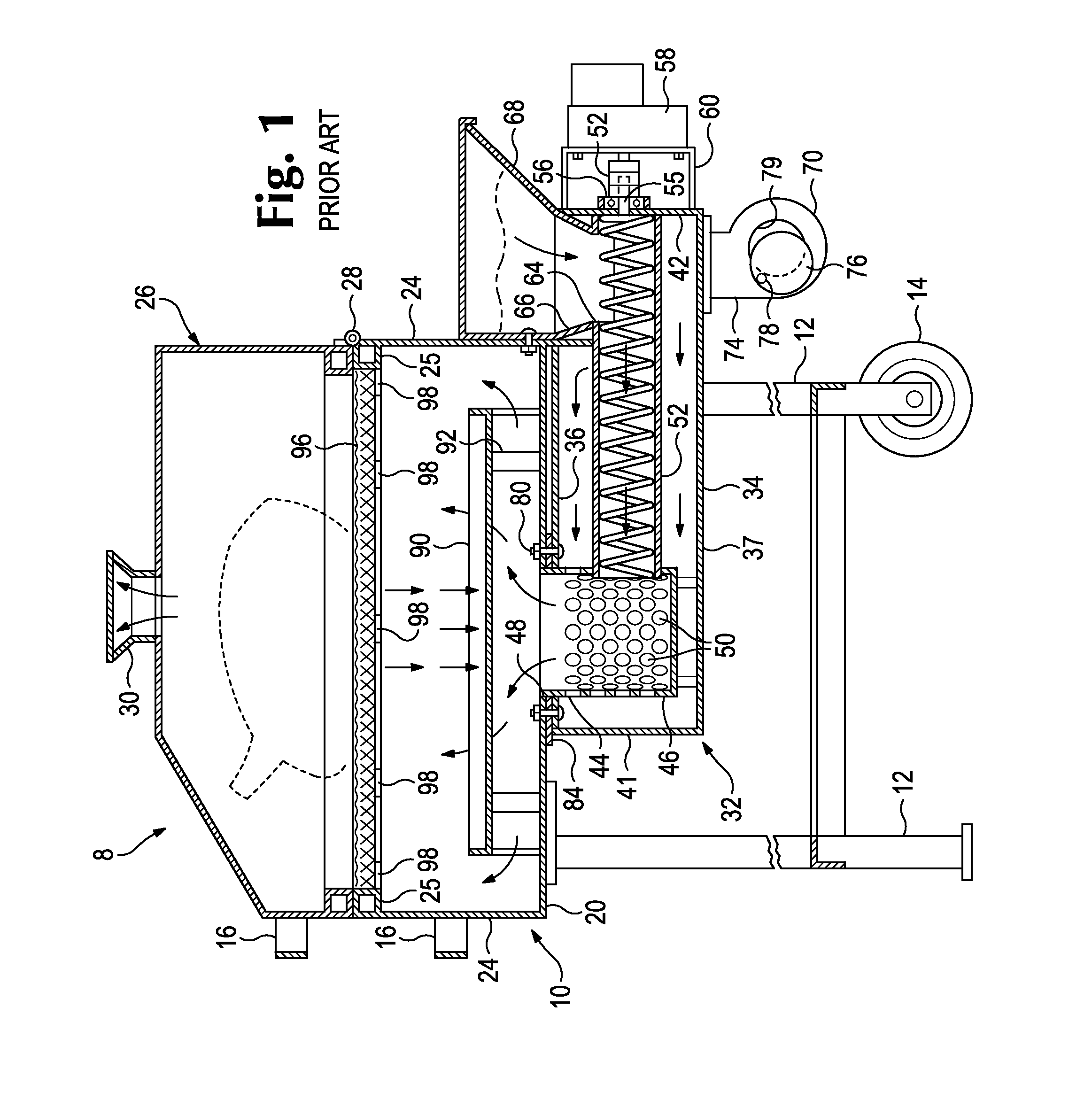
[0012]FIG. 1 is a side elevation, with portions broken away, of a prior art pellet-burning barbecue 8 described in U.S. Pat. No. 4,823,684. Barbecue 8 is configured to place the top of a pan 10 at a convenient working height above the ground, through legs 12 secured to and extending downwardly from the base of the pan 10. For convenience of moving, if desired, wheels 14 are provided rotatably journaled on the base of two of the legs in the barbecue. For moving purposes, the barbecue may be partially raised utilizing handles 16 connected to the pan whereby ground contact is solely through those legs having wheels 14, the barbecue then being rollable to the position desired.

[0013]Pan 10 includes a bottom 20 and opposed side and end walls 22, 24 joined to bottom 20. The top of the pan may be reinforced as by framing 25. Pan 10 is open at the top. If desired, a hinged cover 26 may be included connected by hinges 28 to pan 10. The cover is swingable between a closed position where the co...


PUM


Abstract

A dual-fuel gas-pellet barbecue burner assembly includes a combustion chamber, a pellet burner sub-assembly, and a gas burner sub-assembly. The pellet burner sub-assembly includes a motor-driven auger to deliver fuel pellets to the combustion chamber, and the gas burner sub-assembly includes a gas line that extends into the combustion chamber so that either pellets, gas, or both can be burned in the combustion chamber.

Description

RELATED APPLICATION[0001]This application claims the benefit of U.S. provisional application No. 61 / 818,841, filed May 2, 2013.TECHNICAL FIELD[0002]The present invention relates generally to wood pellet-burning barbecues, and, more particularly, to a dual-fuel gas-pellet burner for use with such barbecues.BACKGROUND OF THE INVENTION[0003]Wood pellet-burning barbecues are popular for outdoor cooking, particularly at homes and in household situations. Conventional wood pellet-burning barbecues, of the type described in U.S. Pat. No. 4,823,684, employ a motor-driven auger to provide a measured feed of wood pellets into a combustion region where the pellets are burned to provide heat and smoke to cook food.[0004]An aspect of such conventional wood pellet-burning barbecues is that the heat generated for larger cooking areas can be limited. While some household barbecues can be large enough to pose such a problem, the issue can become significant in the context of the requirements of comm...

Claims


Application Information

Patent Timeline
IPC IPC(8): A47J37/07
CPCA47J37/0713A47J37/0786A47J37/0704
Inventor TRAEGER, JOE
Owner ORIGINAL PELLET GRILL CO LLC
Why Eureka
Try Eureka