Limit switch

a limit switch and switch technology, applied in the field of limit switches, can solve the problems of lead wire routing and work efficiency degradation, and achieve the effect of improving work efficiency and further facilitating connection work

Active Publication Date: 2014-11-06
ORMON CORP
View PDF3 Cites 7 Cited by
  • Summary
  • Abstract
  • Description
  • Claims
  • Application Information

AI Technical Summary

Benefits of technology

[0007]One or more embodiments of the present invention provides a limit switch in which the connection of the lead wire is easily perform with good work efficiency.
[0009]According to one or more embodiments of the present invention, because the wiring can be performed by routing the lead wire through the projection, the connection work is facilitated to improve the work efficiency. Additionally, the limit switch having an excellent insulating characteristic is obtained because the fixed contact terminals adjacent to each other are partitioned by the projection.
[0011]According to one or more embodiments of the present invention, the work to connect the lead wire can more efficiently be performed.
[0013]According to one or more embodiments of the present invention, a step is generated between the upper and lower fixed contact terminals. Therefore, even if the lead wire is connected to the fixed contact terminal on the lower stage side, the lead wire connected to the fixed contact terminal on the lower stage side does not obstruct the connection work of the fixed contact terminal on the upper stage side, and the efficiency of the connection work is further improved.
[0015]According to one or more embodiments of the present invention, the insulating characteristic is further improved because the insulating wall can prevent the lead wire from abutting directly on an inside surface of the housing.
[0017]According to one or more embodiments of the present invention, because the lead wire can be connected to the fixed contact terminal through the crimped terminal, advantageously the connection work can further be facilitated to improve the work efficiency.

Problems solved by technology

In the conventional limit switch, although work to connect the lead wires to the pair of fixed contact terminals at the lower stage is relatively easy to perform, it takes a lot of work to perform routing of the lead wire when the lead wire is connected to the pair of fixed contact terminals at the upper stage.
Particularly, for the connection of the thick lead wire in a narrow space, it is necessary to fold the lead wire in a complicated way in order to connect the lead wire to the fixed contact terminal at a position different from the drawn position, which results in work efficiency being degraded.

Method used


Image

  • Limit switch
  • Limit switch
  • Limit switch

Examples


Embodiment Construction

[0027]Hereinafter, embodiments of the present invention will be described with reference to FIGS. 1 to 9. In embodiments of the invention, numerous specific details are set forth in order to provide a more thorough understanding of the invention. However, it will be apparent to one of ordinary skill in the art that the invention may be practiced without these specific details. In other instances, well-known features have not been described in detail to avoid obscuring the invention.

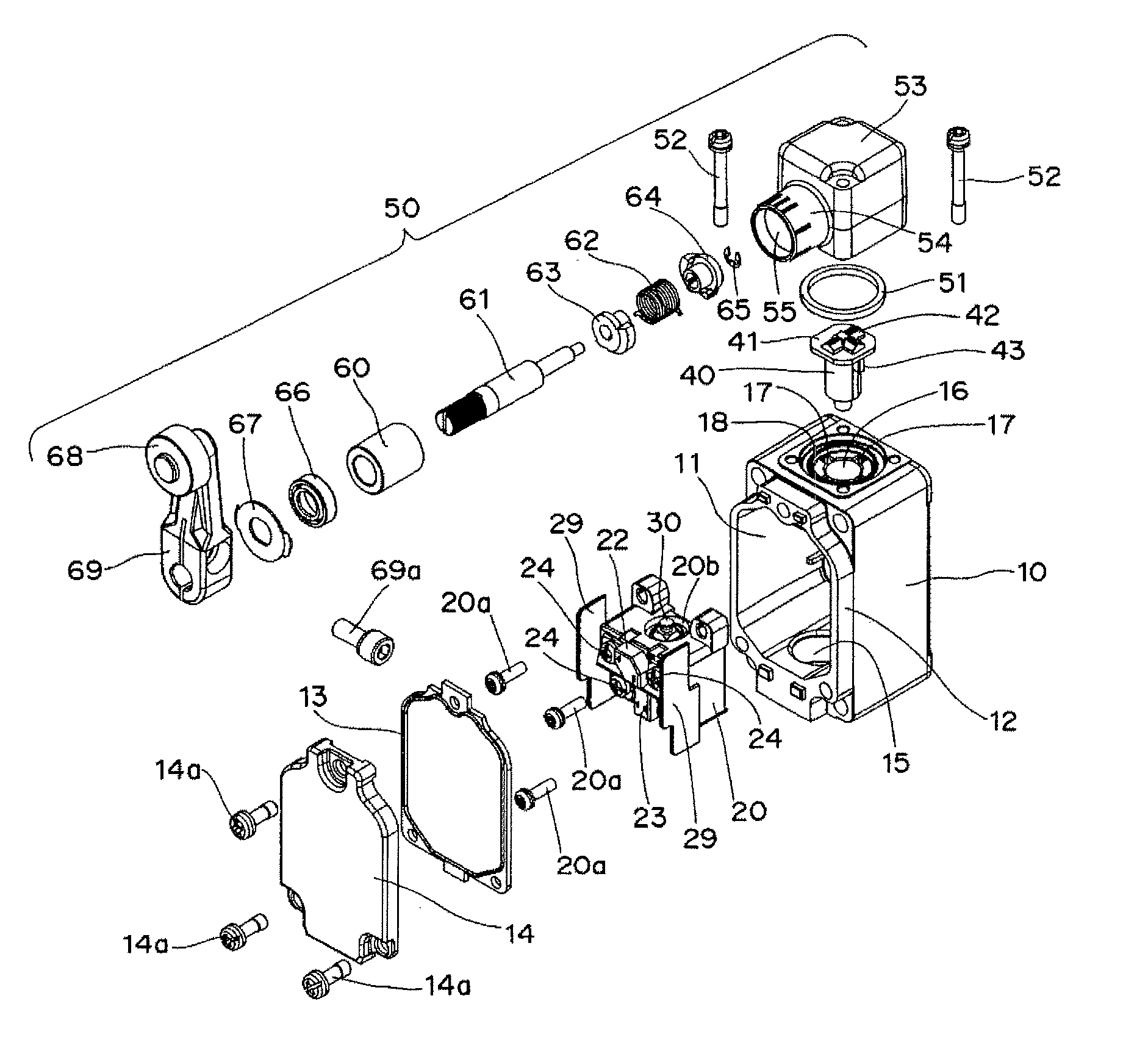
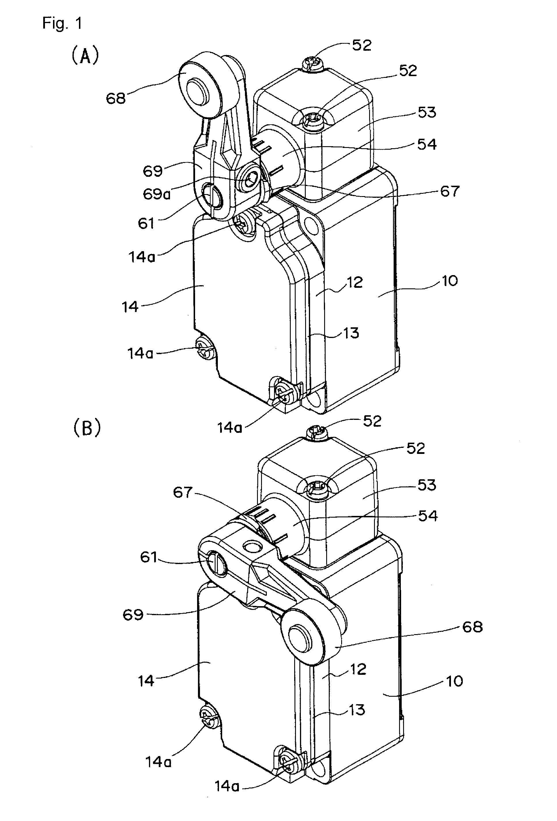
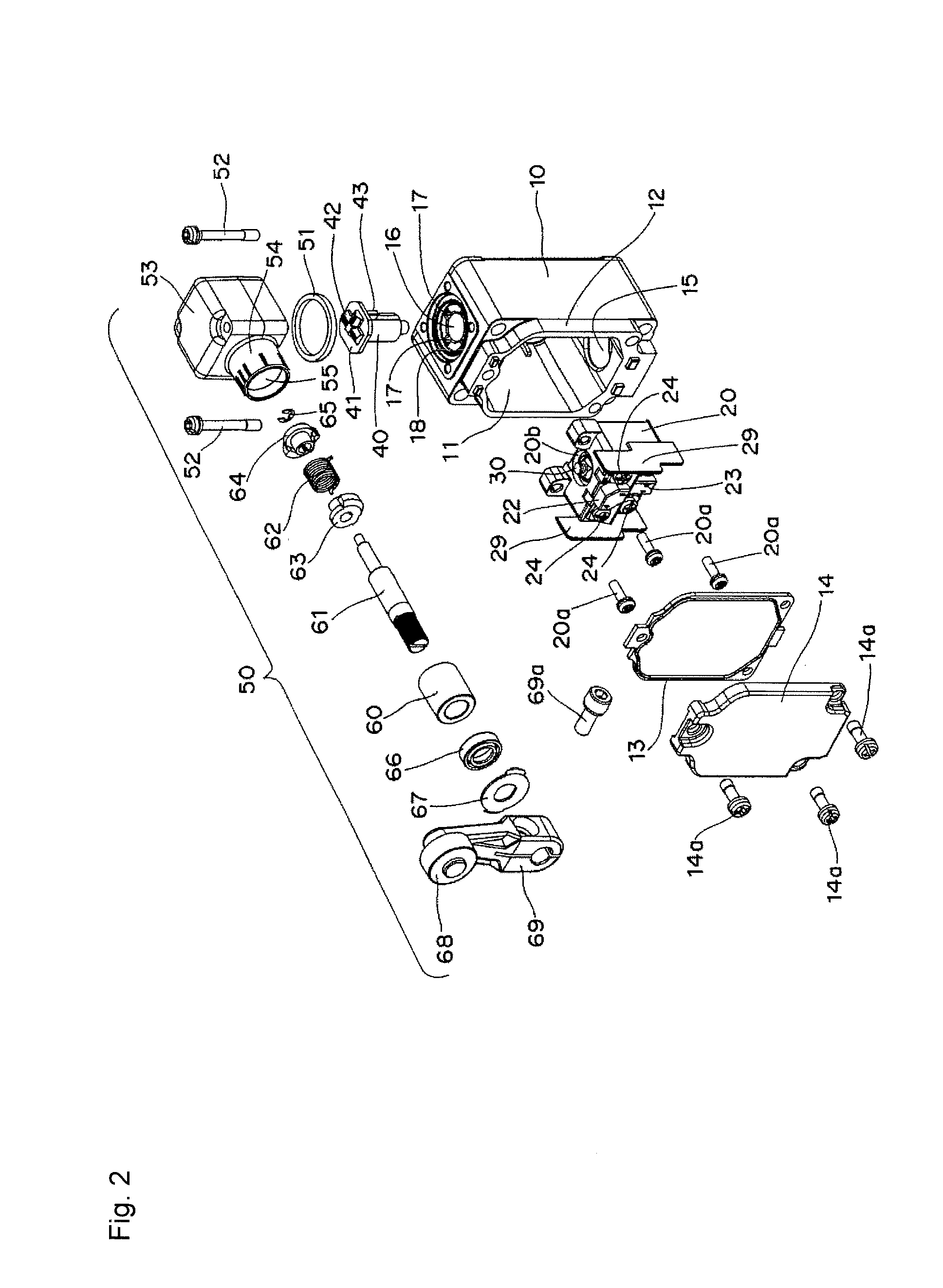
[0028]As illustrated in FIGS. 1 to 3, in a limit switch according to a first embodiment, switch main body 20 assembled in housing 10 is driven by driving mechanism 50 including operation lever 69 through plunger 40.

[0029]Housing 10 has a box shape in which switch main body 20 can be accommodated, and circular rib 12 is formed along opening 11 provided in a front surface of housing 10. Circular seal member 13 is positioned in circular rib 12, and cover 14 is fixed to housing 10 by fixing screws 14a, thereb...


PUM


Abstract

A limit switch has a housing having an opening in a front surface of the housing, and a connection hole in which a lead wire is drawn made in a bottom surface of the housing, a switch main body fixed in the housing, a front surface of which is vertically partitioned into a plurality of stages, a pair of fixed contact terminals embedded at each of the stages, an operation shaft exposed from a ceiling surface of the switch main body, a contact that is opened and closed by driving the operation shaft in a shaft center direction, and a projection provided between the fixed contact terminals embedded at the stages of the front surface of the switch main body.

Description

BACKGROUND[0001]1. Technical Field[0002]The present invention relates to a limit switch, particularly to a wiring structure of a lead wire connected to a fixed contact terminal of the limit switch.[0003]2. Related Art[0004]Conventionally, in the case that the lead wire is connected to the fixed contact terminal of the limit switch, as illustrated in FIG. 3 of Patent Document 1, four lead wires have been drawn through a connection hole (not illustrated) made in a bottom surface of base 1, and a crimped terminal provided at a leading end of the lead wire has been fixed to each of a pair of fixed contact terminals vertically provided at two stages using connection screw.[0005]Patent Document 1: Japanese Unexamined Patent Publication No. 2001-43774SUMMARY[0006]In the conventional limit switch, although work to connect the lead wires to the pair of fixed contact terminals at the lower stage is relatively easy to perform, it takes a lot of work to perform routing of the lead wire when the...

Claims


Application Information

Patent Timeline
Patent Type & Authority Applications(United States)
IPC IPC(8): H01H1/58H01H3/16
CPCH01H1/5855H01H3/16H01H2231/038H01H2207/036H01H2001/5883H01H1/58H01H9/02H01H9/04H01H21/28H01H21/285
Inventor TSUKIMORI, KAZUYUKITAKAHASHI, MANABUMORIYAMA, HIROYUKIFUKUI, SHIGENOBU
Owner ORMON CORP
Why Eureka
Try Eureka