
Vehicle underbody structure

a technology for underbody structures and vehicles, applied in vehicle arrangements, roofs, transportation and packaging, etc., can solve the problem that the collision performance of the vehicle underbody structure in a side collision cannot be satisfactorily guaranteed, and achieve the effect of improving the side collision performan

Inactive Publication Date: 2014-11-06
TOYOTA JIDOSHA KK
View PDF0 Cites 17 Cited by
  • Summary
  • Abstract
  • Description
  • Claims
  • Application Information

AI Technical Summary

Benefits of technology

The present invention is about a vehicle structure that can improve its performance in lateral collisions. This means that the vehicle's design can better resist and absorb the impact of a collision, which can help to protect the occupants from injury and damage.

Problems solved by technology

When the torsional deformation is increased, a rotational deformation, by which the center pillar collapses inward in the width direction of the vehicle body, is increased, and thus a collision performance of the vehicle underbody structure in a side collision cannot be satisfactorily ensured.

Method used


Image

  • Vehicle underbody structure
  • Vehicle underbody structure
  • Vehicle underbody structure

Examples


Embodiment Construction

[0028]Hereinafter, an embodiment of the present invention will be described in detail with reference to the accompanying drawings. The same reference signs will be assigned to the same elements in the description of the drawings, and the repeated descriptions will be omitted.

[0029]First, a vehicle underbody structure according to the embodiment of the present invention will be described with reference to FIGS. 1 to 7.

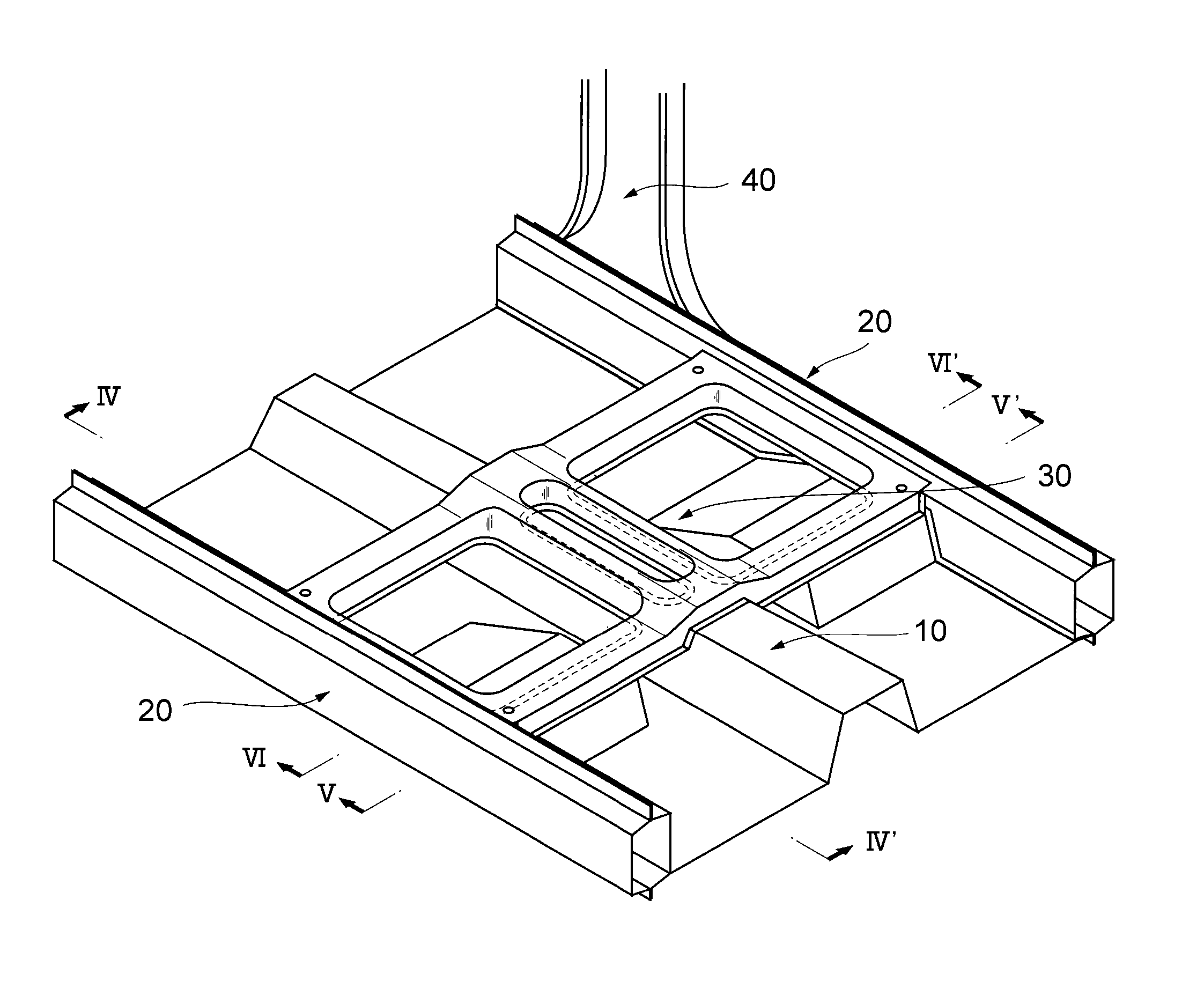
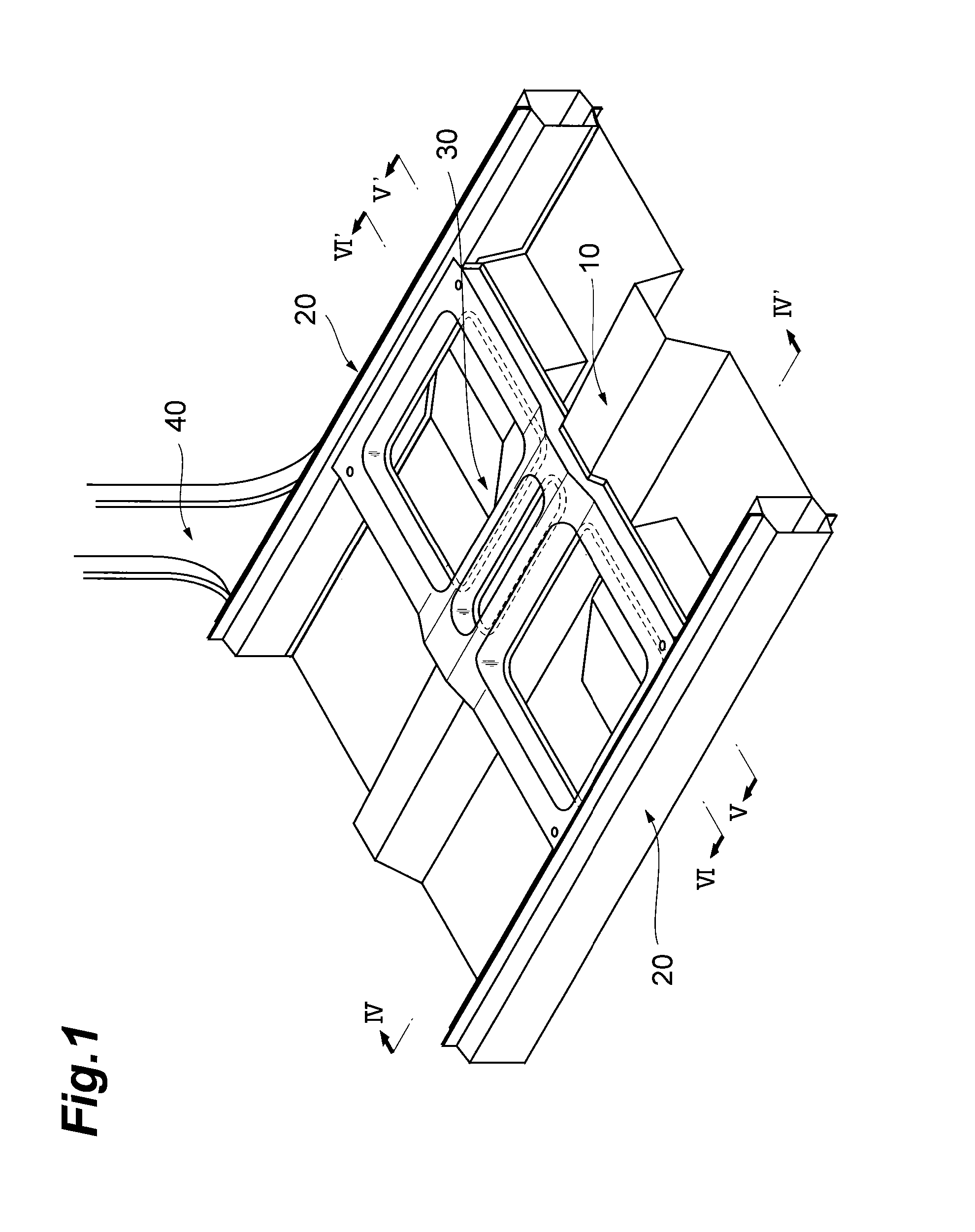
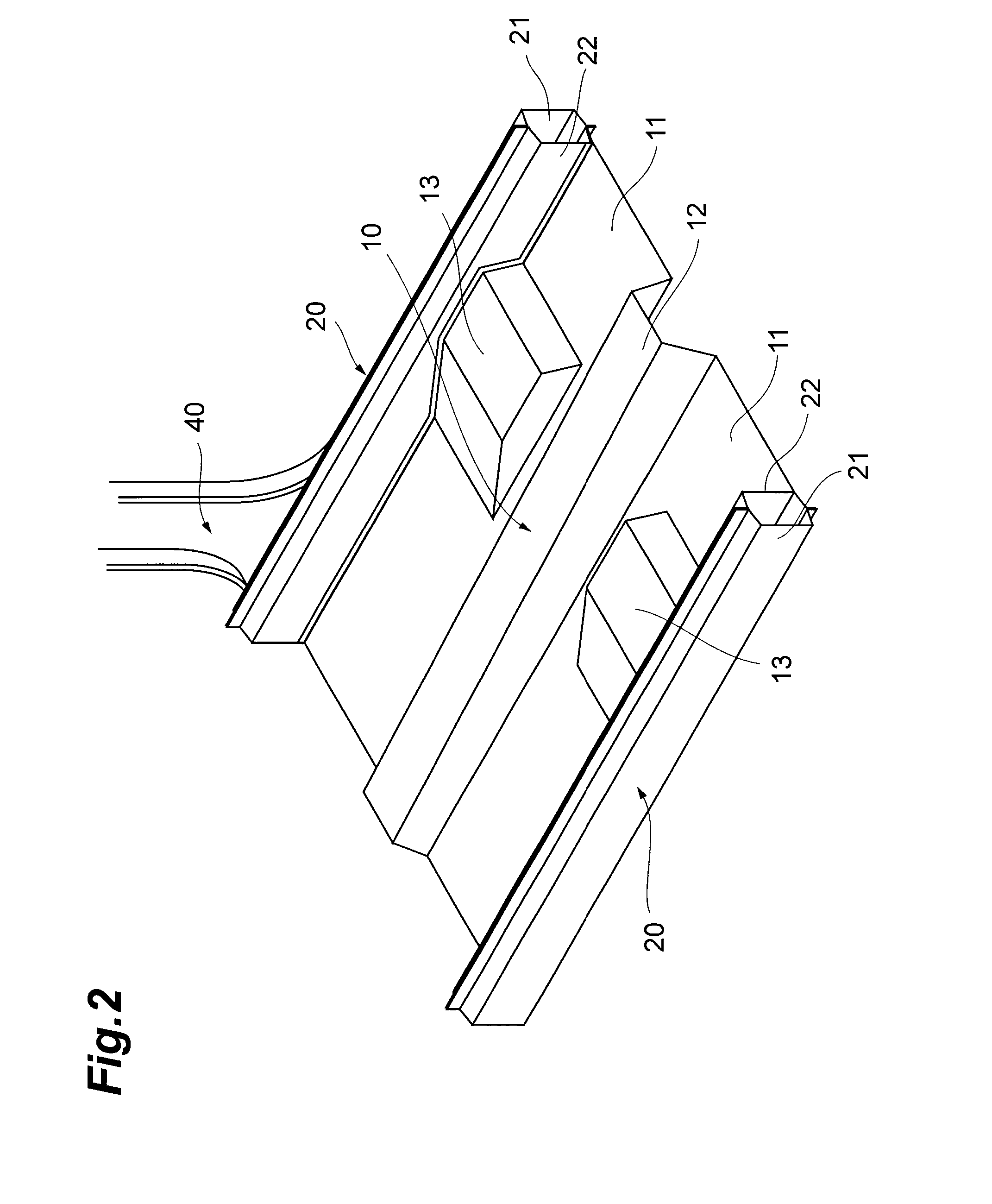
[0030]FIG. 1 is a perspective view illustrating the vehicle underbody structure according to the embodiment of the present invention. As illustrated in FIG. 1, the vehicle underbody structure includes a floor panel 10, a pair of rockers (side sills) 20, and a cross member 30. The floor panel 10 is provided in a lower portion of a vehicle body so as to extend in a longitudinal direction (in a right and left direction in FIG. 1) of the vehicle body. The pair of rockers 20 are respectively provided along right and left sides of the floor panel 10 of the vehicle body so as ...


PUM


Abstract

A vehicle underbody structure includes a floor panel that is provided to extend in a longitudinal direction of a vehicle body; a pair of rockers that are respectively provided along both side portions of the floor panel in the vehicle body to extend in the longitudinal direction of the vehicle body; and a cross member that is mounted in a bridging manner between the pair of rockers to be apart from a floor surface of the floor panel, and that has strength greater than that of the rocker.

Description

TECHNICAL FIELD[0001]The present invention relates to a vehicle underbody structure.BACKGROUND ART[0002]In the related art, for example, Japanese Unexamined Patent Application Publication No. 2000-168627 discloses a vehicle underbody structure that efficiently absorbs energy in a side collision. The vehicle underbody structure has a Z-shaped portion in a cross member, which is positioned in the vicinity of a tunnel portion of a floor panel, and thus the vehicle underbody structure suppresses an occurrence of a moment in a center pillar in a side collision, and absorbs energy.[0003]When a collision load is exerted on the center pillar and the like, a rotational moment about a longitudinal axis is exerted on a rocker (a side sill) that is joined with a lower portion of the center pillar, and a torsional deformation occurs so that an upper portion of the rocker collapses inward in a width direction of a vehicle body. When the torsional deformation is increased, a rotational deformation...

Claims


Application Information

Patent Timeline
Patent Type & Authority Applications(United States)
IPC IPC(8): B62D21/15
CPCB62D21/157B62D25/2036B62D25/20
Inventor MORI, TAKEO
Owner TOYOTA JIDOSHA KK
Learn More