Driver device and driving method for driving a capacitive load, in particular an ultrasound transducer

a technology of capacitive load and drive device, which is applied in the direction of piezoelectric/electrostrictive device details, piezoelectric/electrostrictive/magnetostrictive devices, mechanical vibration separation, etc., can solve the problems of limited efficiency and limited power factor of existing ultrasound transducers, and achieve the effect of reducing the increased coupling factor and increasing the power factor

Active Publication Date: 2014-11-06
KONINKLJIJKE PHILIPS NV
View PDF4 Cites 2 Cited by
  • Summary
  • Abstract
  • Description
  • Claims
  • Application Information

AI Technical Summary

Benefits of technology

[0005]It is therefore an object of the present invention to provide an improved driver device and a corresponding driving method for driving a capacitive load, in particular an ultrasound transducer having one or more transducer elements, providing an increased power factor and a reduced increased coupling factor. Further, it is an object of the present invention to provide a corresponding ultrasound apparatus.

Problems solved by technology

The existing ultrasound transducers have a limited power factor and a limited efficiency due to a limited coupling factor.

Method used


Image

  • Driver device and driving method for driving a capacitive load, in particular an ultrasound transducer
  • Driver device and driving method for driving a capacitive load, in particular an ultrasound transducer
  • Driver device and driving method for driving a capacitive load, in particular an ultrasound transducer

Examples


first embodiment

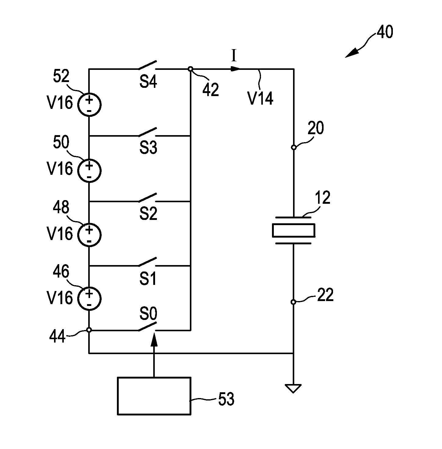
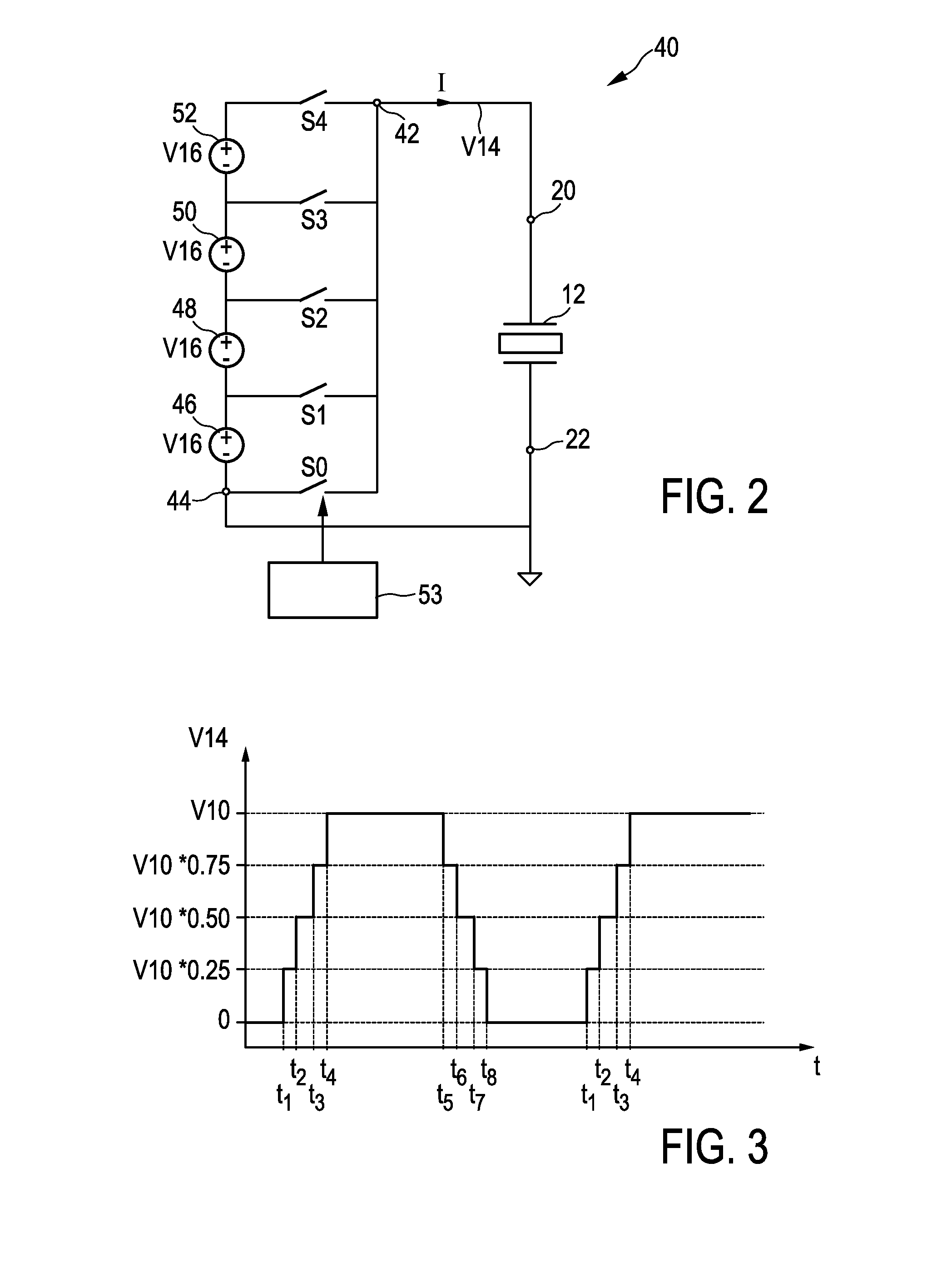
[0042]FIG. 2 shows a schematic block diagram of a driver device according to the present invention. The driver device in FIG. 2 is generally denoted by 40.

[0043]The driver device 40 comprises an output terminal 42 to provide an output voltage V14 and a drive current I to the ultrasound transducer 12. The driver device 40 comprises a second output terminal 44, which is connected to neutral or a bias voltage (dependent on the used transducer type).

[0044]The driver device 40 comprises four voltage supply elements 46, 48, 50, 52. Each of the voltage supply elements 46-52 provides an intermediate voltage V16 as a partial voltage V16 of the supply voltage V10. A sum of the intermediate voltage levels V16 is identical with the supplied voltage V10. The intermediate voltage levels V16 are preferably identical and in this embodiment V16=0.25*V10. In an alternative embodiment, the intermediate voltage levels V16 are different from each other, wherein the sum of the intermediate voltage levels...

second embodiment

[0054]FIG. 6 shows a driver device according to the present invention. The driver device in FIG. 5 is generally denoted by 60. The driver device 60 comprises a first portion 62 and a second portion 64. The first portion 62 is connected to the first input terminal 20 of the ultrasound transducer 12 and the second portion 64 is connected via a capacitor 66 to the second input terminal 22 of the ultrasound transducer 12.

[0055]The first portion 62 comprises a first output terminal 68 and a second output terminal 70. The first output terminal 68 is connected to the first input terminal 20 of the ultrasound transducer 12. The second output terminal 70 is connected to neutral. The first portion 62 comprises two voltage supply elements 72, 74 connected in series to each other. The voltage supply elements 72, 74 each provide the intermediate voltage V16. The first portion 62 further comprises three controllable switches S5, S6, S7. The controllable switches S5, S6, S7 are connected to the fi...


PUM


Abstract

The present invention relates to a driver device (40; 60) for driving a capacitive load (12), in particular an ultrasound transducer (12) having one or more transducer elements, comprising an output terminal (42; 68) for providing an alternating drive voltage (V14; V22) to the load (12), a plurality of voltage supply elements (46, 48, 50, 52; 72, 74) for providing intermediate voltage levels (V16), a plurality of controllable connecting means (S0-S7) each associated to one of the voltage supply elements (46, 48, 50, 52; 72, 74) for connecting the voltage supply elements (46, 48, 50, 52; 72, 74) to the output terminal (42; 68) and for supplying one of the intermediate voltage levels (V16) or a sum of a plurality of the intermediate voltage levels (V16) as the alternating drive voltage (V14; V22) to the output terminal.

Description

FIELD OF THE INVENTION[0001]The present invention relates to a driver device and a corresponding driving method for driving a capacitive load, in particular an ultrasound transducer comprising one or more transducer elements. Further, the present invention relates to an ultrasound apparatus.BACKGROUND OF THE INVENTION[0002]In the field of ultrasound transducers the use of piezoelectric transducers such as lead zirconate titanate (PZT) transducers and, nowadays, MEMS transducers such as capacitive micro-machined ultrasound transducer (cMUT) devices is common practice for providing two or three dimensional ultrasound waves. The micro-machined technology in this field allows small feature sizes and the realization of high-frequency beam-forming arrays, which can be formed monolithically on the same wafer.[0003]The existing ultrasound transducers have a limited power factor and a limited efficiency due to a limited coupling factor. The coupling factor of ultrasound transducers represent...

Claims


Application Information

Patent Timeline
Patent Type & Authority Applications(United States)
IPC IPC(8): H01L41/04
CPCH01L41/042B06B1/023H10N30/802
Inventor VAN RENS, ANTONIA CORNELIA
Owner KONINKLJIJKE PHILIPS NV
Why Eureka
Try Eureka