Axial Turbomachine Stator with Ailerons at the Blade Roots

a turbomachine and stator technology, applied in the direction of stators, machines/engines, liquid fuel engines, etc., can solve the problems of stalling still occurring on the suction side of the blades, and reducing the efficiency of the turbomachin

Active Publication Date: 2014-11-06
TECHSPACE AERO
View PDF7 Cites 30 Cited by
  • Summary
  • Abstract
  • Description
  • Claims
  • Application Information

AI Technical Summary

Problems solved by technology

In operation, the annular flow may break away from the blades, thus creating entropy that reduces the turbomachine's efficiency.
However, stalling can still occur on the su

Method used


Image

  • Axial Turbomachine Stator with Ailerons at the Blade Roots
  • Axial Turbomachine Stator with Ailerons at the Blade Roots
  • Axial Turbomachine Stator with Ailerons at the Blade Roots

Examples


Embodiment Construction

[0015]The present application aims to solve at least one of the problems presented by the prior art. More specifically, the present application aims to improve the capacity of a stator to straighten a flow. More specifically, the present application aims to increase the output pressure of a bladed stator. The present application also aims to improve the performance of a compressor with a bladed stator.

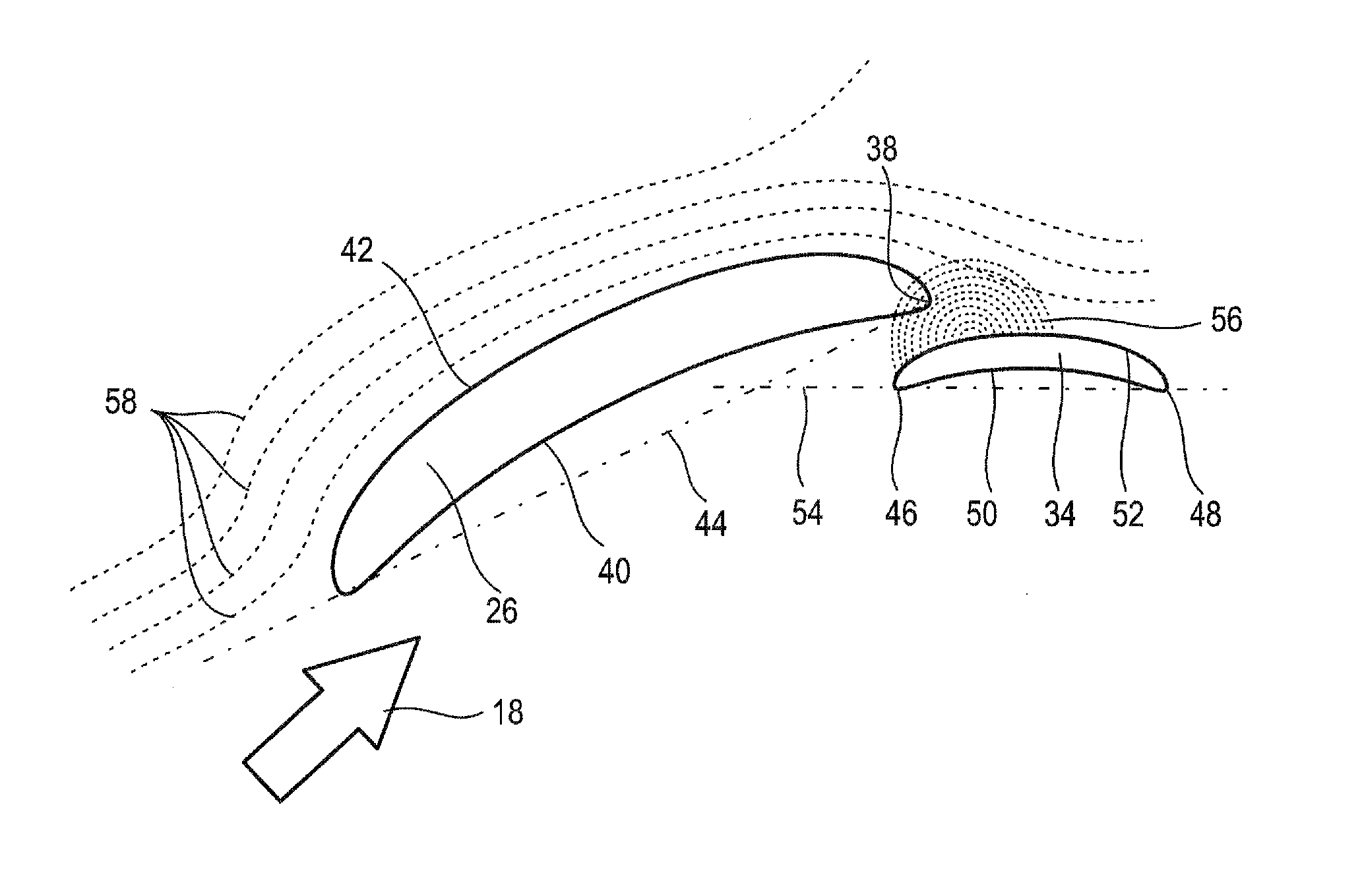
[0016]The present application relates to an axial stator of a turbomachine, comprising: a main annular row of stator blades extending radially, each of the said blades comprising a pressure side and a suction side; a series of auxiliary stator blades arranged between the main blades; wherein each of the auxiliary blades is associated with one of the main blades extending along and downstream of the pressure face of the associated primary blade, at a distance, in a circumferential direction, which is less than 30% of the distance between two neighbouring main blades.

[0017]According to a...


PUM


Abstract

The present application relates to the compressor stator of an axial turbomachine. The stator comprises an annular row of main stator blades and auxiliary blades each of which are associated with a main blade. The auxiliary blades are located at the trailing edges of the main blades and are in the vicinity of the pressure faces of the main blades. The auxiliary blades are aligned to generate a low-pressure area at the trailing edges of the main blades. Thus, a flow bypassing a main blade by its suction face is sucked in by the low-pressure area when it approaches the trailing edge of the main blade. Stalling is thus avoided and the efficiency of the machine is improved.

Description

[0001]This application claims priority under 35 U.S.C. §119 to European Patent Application No. 13166527.5, filed 3 May 2013, which is incorporated herein by reference for all purposes.BACKGROUND[0002]1. Field of the Application[0003]The present application relates to the stator of an axial compressor. More particularly, the present application relates to a stator of an axial turbomachine comprising main blades and auxiliary blades associated with the main blades. The present application also relates to an axial turbomachine fitted with a stator in accordance with the present application.[0004]2. Description of Related Art[0005]In order to straighten their annular flows, axial turbomachines have stators. These arrays of blades are located downstream of each annular row of rotor blades. They deflect an annular flow so as to convert the tangential component into an axial component. This flow is then able to be re-accelerated by a further annular array of rotor blades located downstream...

Claims


Application Information

Patent Timeline
IPC IPC(8): F01D5/14F04D29/54
CPCF04D29/542F01D5/142F01D5/146F01D9/041F04D29/681F04D29/544Y02T50/60
Inventor DERCLAYE, ALAINDEPAEPE, DAVID
Owner TECHSPACE AERO
Why Eureka
Try Eureka